
Ship turning motion simulation method

A technology of rotary motion and simulation method, applied in special data processing applications, instruments, electrical digital data processing, etc., which can solve the problems of unrealistic ships or submarines, large number of grids, and high computing power requirements, so as to avoid flow field Calculation is unstable, meets calculation needs, and improves the effect of simulation accuracy

Active Publication Date: 2019-02-12
NAVAL UNIV OF ENG PLA
View PDF4 Cites 10 Cited by
  • Summary
  • Abstract
  • Description
  • Claims
  • Application Information

AI Technical Summary

Problems solved by technology

However, the momentum source term is added to the average Reynolds equation system (RANS), which makes the calculation and solution more complicated; and in the process of numerical simulation, the submarine has no thrust and is only washed by the incoming current, so the submarine can only be roughly analyzed It is difficult to accurately simulate the rotary motion of the submarine under the action of propeller thrust and rudder force
The traditional overlapping grid technology can simulate ship movement by setting overlapping grids and interfaces around the hull. The overlapping grids exchange information with the background domain during movement, but this method needs to set the space required for ship movement as the background domain and divide the grid, for the rotary motion, the required background domain is too large, the number of grids is too large, it is unrealistic to simulate a large rotary ship or submarine
To simulate propeller thrust, the existing method is to build a 3D model of the propeller and draw overlapping grids, but the workload is heavy, the number of grids is too large, the calculation time is too long, and the computing power is too high
It is not conducive to shortening the ship design cycle and reducing the design cost
Apply the method of virtual paddle disk body force to simulate the thrust of the ship, fix the forward and backward movement of the hull, and determine the flow velocity that matches the current thrust by changing the incoming flow velocity of the water, which is the current velocity of the hull. This method requires multiple times The current speed can only be determined by calculation, and the unsteady motion of the hull cannot be truly simulated

Method used


Image

  • Ship turning motion simulation method
  • Ship turning motion simulation method
  • Ship turning motion simulation method

Examples


Embodiment Construction

[0033] The invention will be described in detail below in conjunction with specific embodiments.

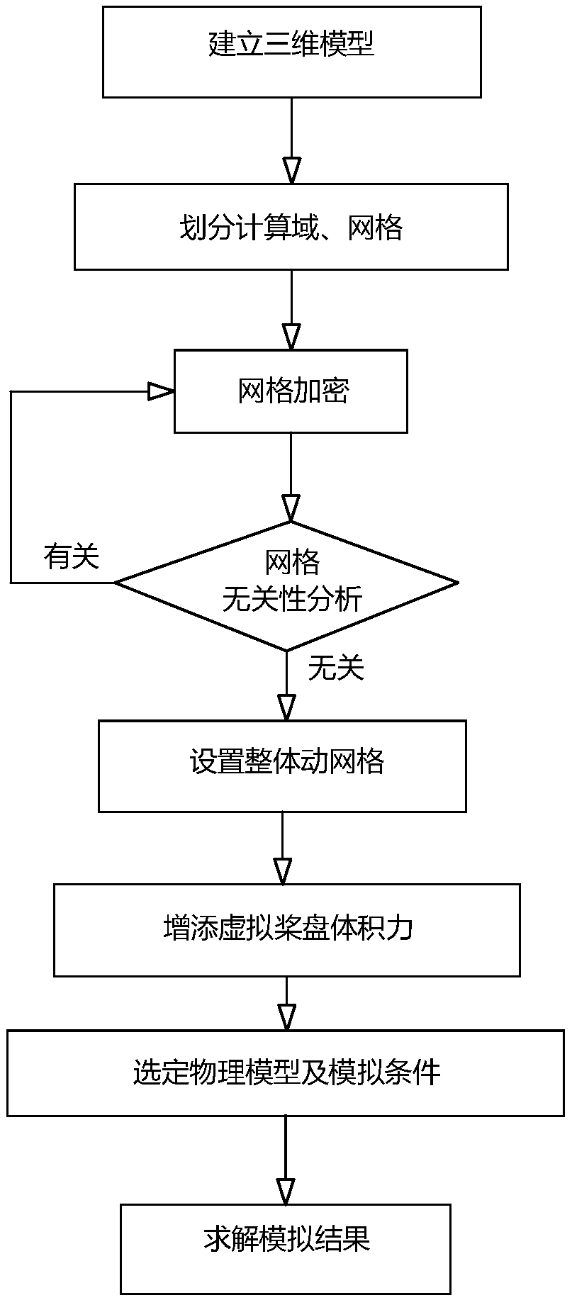
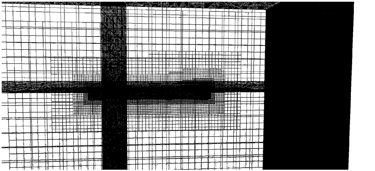
[0034] refer to Figure 1 to Figure 5 , a method for simulating the turning motion of a ship provided by the present invention, its flow chart is as follows figure 1 shown. Its basic steps include:

[0035] Step 1: Establish a three-dimensional model of the ship, adjust the rudder angle according to the needs of the simulated movement, and determine the geodetic coordinate system and the satellite coordinate system; specifically,

[0036] 1.1 Establish a three-dimensional model of the ship through modeling software such as rhino, etc. The model should include the hydrodynamic shape of the ship and the shape of the control surface, excluding the model of the propeller and other thrust devices, and rotate the rudder of the ship to the predetermined rudder angle; this implementation The ship in the example is a self-propelled model of a certain type of ship. The model established...


PUM


Abstract

The invention belongs to the technical field of ship motion measurement, in particular to a ship turning motion simulation method. The method does not model a propeller, but simulates propeller thrustwith virtual paddle volume force, and simulates ship or submarine rotating motion in water with integral dynamic mesh, so that the simulation precision is improved and the modeling difficulty is simplified, and accordingly designers and testers can quickly and accurately predict the hydrodynamic performance of the ship 's gyration.

Description

technical field [0001] The invention belongs to the technical field of ship motion measurement, in particular to a ship turning motion simulation method. Background technique [0002] Ship slewing performance is one of the important ship maneuverability indicators. Ships with good slewing performance are easy to steer and maneuver when navigating at sea, which is convenient to bypass other ships or obstacles, and avoid collision accidents, which is of great significance to the safe navigation of ships. Prediction of slewing performance is an important step in the design process of a ship or submarine. The traditional slewing performance prediction method is to carry out slewing experiments of real ships or ship models, but such experiments are time-consuming and laborious, prolonging the ship design cycle and increasing the cost of ship design. With the development of computer performance, computational fluid dynamics (CFD) method is often used in the calculation of ship h...

Claims


Application Information

Patent Timeline
Patent Type & Authority Applications(China)
IPC IPC(8): G06F17/50
CPCG06F2119/06G06F30/23Y02T90/00
Inventor 肖昌润李士强曹植珺梁秋凤
Owner NAVAL UNIV OF ENG PLA
Learn More