
Rock Porosity Restoration Method During Hydrocarbon Accumulation Period in Superimposed Basins

A technology of rock porosity and superimposed basins, applied in the field of oil and gas geological exploration, can solve the problems of heavy workload, difficult restoration of ancient porosity, and large distribution range, and achieve the effect of wide application

Active Publication Date: 2020-07-14
CHINA PETROLEUM & CHEM CORP +1
View PDF4 Cites 0 Cited by
  • Summary
  • Abstract
  • Description
  • Claims
  • Application Information

AI Technical Summary

Problems solved by technology

The disadvantage of the compaction trend method is that it does not consider the influence of other factors, and in terms of the pore-depth relationship, the porosity distribution range at the same depth is relatively large, which makes it difficult to restore the ancient porosity.
The disadvantages of the inversion backstripping method are: this method has great limitations in practical application. First, this method has a large workload and requires a variety of data, which is only suitable for areas with relatively high degree of exploration; Secondly, this method also has certain requirements for the reservoir, for example, the matrix content of the reservoir is relatively low, fractures should not develop, and the particle size should be moderate; third, there are still some difficulties and problems in this method, such as in On the stage distinction of multi-cycle diagenesis types, on the conversion of surface porosity to porosity, how to calculate the influence of clay mineral cement on reservoir physical properties, etc.

Method used


Image

  • Rock Porosity Restoration Method During Hydrocarbon Accumulation Period in Superimposed Basins
  • Rock Porosity Restoration Method During Hydrocarbon Accumulation Period in Superimposed Basins
  • Rock Porosity Restoration Method During Hydrocarbon Accumulation Period in Superimposed Basins

Examples


Embodiment Construction

[0067] In order to make the above and other objects, features and advantages of the present invention more comprehensible, the preferred embodiments are listed below and shown in the accompanying drawings in detail as follows.

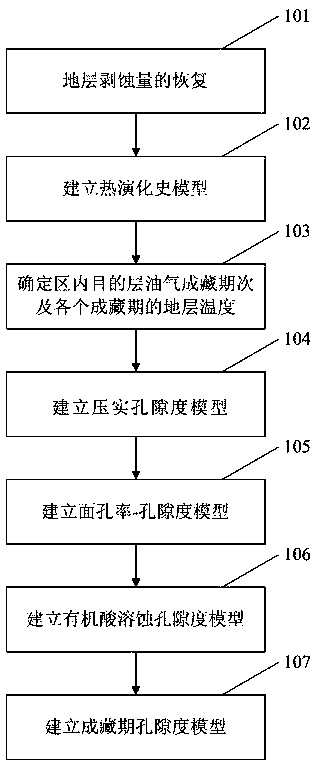
[0068] like figure 1 as shown, figure 1 It is a flow chart of the rock porosity recovery method in superimposed basin oil and gas accumulation period of the present invention.

[0069] Step 101, recovery of stratum denudation amount

[0070] Due to the impact of tectonic movement, the formation will be denuded during the uplift process, so the denudation amount of the strata needs to be restored. Using the acoustic wave transit time curve, select the acoustic wave transit time curve corresponding to the mudstone section with a thickness of not less than 1.5m for curve fitting, restore the erosion amount, and then restore the erosion amount of the formation in different geological historical periods;

[0071] Wherein, the concrete steps of step 101 a...


PUM


Abstract

The invention provides a superimposed basin oil gas pool-forming period rock porosity recovering method. The superimposed basin oil gas pool-forming period rock porosity recovering method comprises the steps that Step 1, recovery of stratum denudation quantity is carried out; Step 2, a thermal evolution history model is established; Step 3, pool-forming periods of target layer oil gas in an area and stratus temperatures of all the pool-forming periods are determined; Step 4, a compaction porosity model in the process of burying is established; Step 5, a surface-porosity-porosity model is established; Step 6, an organic acid corrosion porosity model in the process of burying is established; and Step 7, according to the compaction porosity model in the Step 4 and the organic acid corrosion porosity model established in the Step 6, a pool-forming period porosity model is established. The superimposed basin oil gas pool-forming period rock porosity recovering method enriches a quantitativeevaluation of corrosion porosity in the processes of multi-period pool-forming, can be widely applied to an evaluation of porosity in the process of superimposed basin multi-period pool-forming, andhas important guiding significancesfor oil gas exploration.

Description

technical field [0001] The invention relates to the technical field of oil and gas geological exploration, in particular to a method for restoring rock porosity during the oil and gas accumulation period in superimposed basins. Background technique [0002] Low-permeability oil and gas resources occupy a very important position in my country's oil and gas resources, and are also the main targets of future oil and gas exploration in China. The formation of low-permeability reservoirs is mainly affected by sedimentation and later diagenesis. Sedimentation mainly controls the physical properties of reservoirs, while compaction and cementation in diagenesis can damage the physical properties of reservoirs, and dissolution can improve reservoir properties. Layer property. Most of the existing reservoir evaluation systems are static evaluations, and the reservoir physical properties in the critical accumulation period that really determine whether oil and gas enter the reservoir ...

Claims


Application Information

Patent Timeline
Patent Type & Authority Patents(China)
IPC IPC(8): G01V1/50
CPCG01V1/50
Inventor 马雪洁吕铁良曲彦胜肖雄飞王圣柱于洪洲牛晓燕赵玉峰赵建成李佳
Owner CHINA PETROLEUM & CHEM CORP
Learn More