
A multifunctional cutting machine

A cutting machine and multi-functional technology, applied in metal processing, etc., can solve the problems of high labor consumption and low work efficiency, and achieve the effects of high work efficiency, improved efficiency, and convenient cleaning and replacement

Active Publication Date: 2020-12-01
李聚稳
View PDF8 Cites 1 Cited by
  • Summary
  • Abstract
  • Description
  • Claims
  • Application Information

AI Technical Summary

Problems solved by technology

[0003] If a chef cuts a large amount of fruits and vegetables, it will not only consume a lot of labor, but also the work efficiency is low, so in order to meet the huge demand, there is an urgent need for a multifunctional cutting machine on the market to solve the problem of conveniently cutting a large amount of fruits and vegetables

Method used


Image

  • A multifunctional cutting machine
  • A multifunctional cutting machine
  • A multifunctional cutting machine

Examples


Embodiment 1

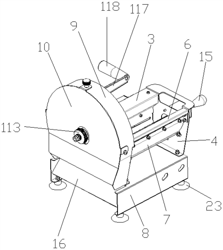
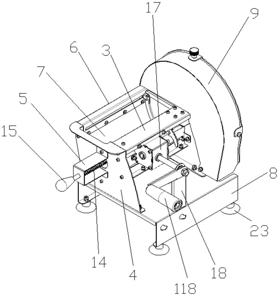
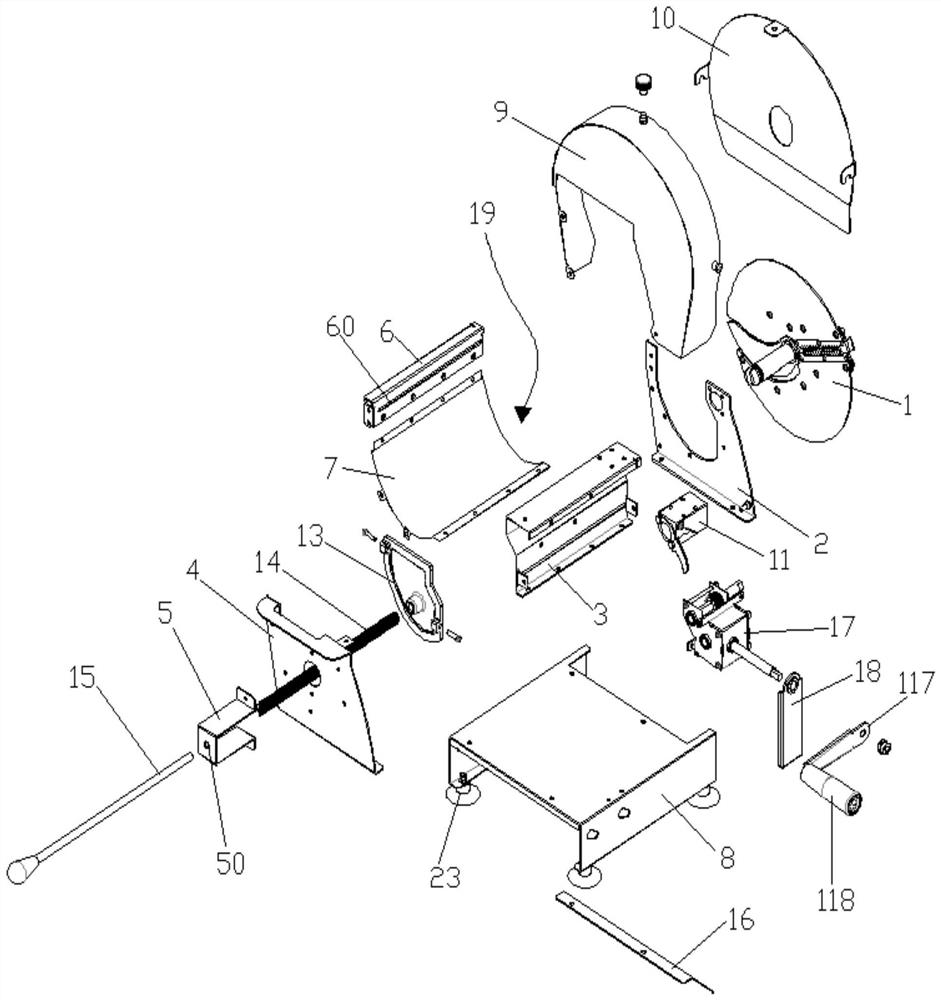
[0057] Embodiment one: if Figure 1 to Figure 17 The first embodiment of a multifunctional cutting machine shown includes a mounting frame, a cutter head 1, a cutting knife 103 and a governor 17, and the mounting frame includes a base 8 and an axle seat plate 3, and the axle seat The plate 3 is connected to the upper surface of the base 8, and the outer side of the shaft seat plate 3 is connected with a speed governor 17, and the two sides of the speed governor 17 extend out a shaft body, and the shaft body rotates freely, and the shaft body on one side is The output shaft 201, the shaft body on the other side is the input shaft 213, the middle point of the side of the cutterhead 1 is pierced with a rotating shaft 101, and the output shaft 201 of the governor 17 is connected to the rotating shaft 101 of the cutterhead 1 through transmission. A shaft seat assembly 11 is sleeved between the output shaft 201 and the rotating shaft 101 , and the cutting knife 103 is embedded in th...

Embodiment 2

[0084] Embodiment two: if Figure 1 to Figure 7 and Figure 17 to Figure 20 Embodiment 2 shown: In this embodiment 2, the cutter head 1 includes a cutter head panel 302, a cutter head middle plate 303, a cutter head rear plate 304, a fixing seat 110, a main shaft 111, an adjustment knob 113, a handle connection Rod 117, handle 118, handle shaft 119;

[0085] One end of the main shaft 111 passes through the fixed seat 110, the cutter head rear plate 304, the cutter head middle plate 303, the cutter head panel 302 and the cutting knife 103 in turn, and is connected with the rotating shaft 101. The shape of the cutting knife 103 is "S" ;

[0086] The other end of the main shaft 111 away from the fixing seat 110 is sequentially provided with an adjusting knob 113 and a handle connecting rod 117, which are connected and fixed by nuts;

[0087] A handle 118 is connected to the end of the handle connecting rod 117 away from the adjustment knob 113, and a handle shaft 119 is pierce...


PUM


Abstract

The invention provides a multifunctional cutting machine. A shaft seat plate of the multifunctional cutting machine is connected to the upper surface of a base. A speed adjuster is connected with theouter side of the shaft seat plate. Shaft bodies extend out from the two sides of the speed adjuster. The shaft bodies move and rotate. The shaft body on one side is an output shaft. The shaft body onthe other side is an input shaft. A rotating shaft is arranged at the midpoint of the side face of a cutter disk in a penetrating manner. An output shaft of the speed adjuster is in transmission connection with the rotating shaft of the cutter disk. A shaft seal assembly is arranged between the output shaft and the rotating shaft in a sleeving manner. A cutting cutter is embedded into the cutterdisk. When the multifunctional cutting machine is in use, vegetables and fruits are placed in a food groove, a push rod is pushed to push the vegetables and fruits to make contact with the cutter disk, and a handle of the speed adjuster is rotated, so that the output shaft of the speed adjuster is made to drive the rotating shaft to rotate, then the cutter disk is driven to rotate, and in this way, cutting machining of the vegetables and fruits is achieved. Therefore, time and effort are saved, and the work efficiency is high.

Description

technical field [0001] The invention belongs to the technical field of cutting machines, in particular to a multifunctional cutting machine. Background technique [0002] In modern society, with the improvement of living standards, people often consume in hotel restaurants, so hotel restaurants need to cut a large amount of fruits and vegetables every day to prepare materials in advance. [0003] If a large amount of fruits and vegetables are cut by a chef, it will not only consume a large amount of labor, but also work efficiency is low, so in order to meet the huge demand, there is an urgent need for a multifunctional cutting machine on the market now to solve the problem of conveniently cutting a large amount of fruits and vegetables. Contents of the invention [0004] In order to solve the above technical problems, the present invention provides a multifunctional cutting machine. [0005] In order to achieve the above object, the present invention provides the followi...

Claims


Application Information

Patent Timeline
Patent Type & Authority Patents(China)
IPC IPC(8): B26D1/29B26D7/26B26D5/10
CPCB26D1/29B26D5/10B26D7/2614B26D2210/02
Inventor 李聚稳
Owner 李聚稳
Learn More