
Angle locating and locking mechanism

A locking mechanism and angle positioning technology, which is applied in the direction of workpiece clamping devices and manufacturing tools, can solve the problems of inability to achieve fine adjustment and high positioning costs, and achieve the effects of simple and compact structure, angle positioning, and high-precision angle positioning

Inactive Publication Date: 2019-02-12
GUANGZHOU HAOZHI ELECTROMECHANICAL
View PDF4 Cites 0 Cited by
  • Summary
  • Abstract
  • Description
  • Claims
  • Application Information

AI Technical Summary

Problems solved by technology

[0003] In order to overcome the deficiencies of the prior art, one of the objectives of the present invention is to provide an angle positioning locking mechanism, which can solve the existing problems of high positioning cost and inability to realize fine adjustment

Method used

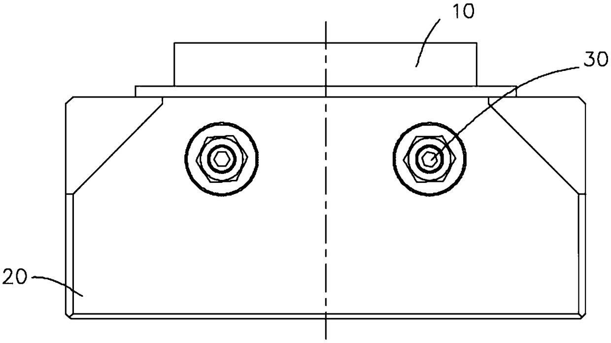
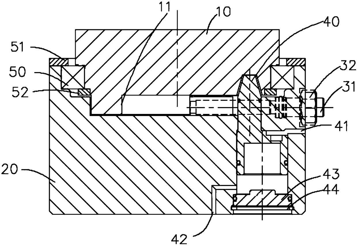
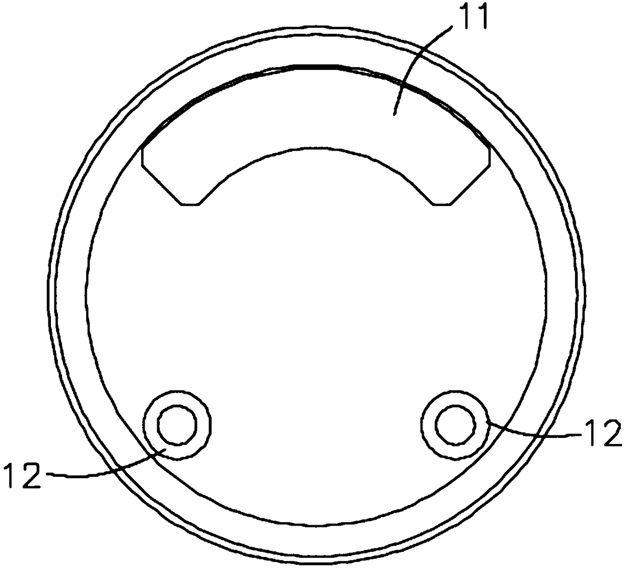

Image

  • Angle locating and locking mechanism
  • Angle locating and locking mechanism
  • Angle locating and locking mechanism

Examples


Embodiment Construction

[0023] Below, the present invention will be further described in conjunction with the accompanying drawings and specific implementation methods. It should be noted that, under the premise of not conflicting, the various embodiments described below or the technical features can be combined arbitrarily to form new embodiments. .

[0024] It should be noted that when a component is said to be "fixed" to another component, it can be directly on the other component or there can also be an intervening component. When a component is said to be "connected" to another component, it may be directly connected to the other component or there may be intervening components at the same time. When a component is said to be "set on" another component, it may be set directly on the other component or there may be an intervening component at the same time. The terms "vertical," "horizontal," "left," "right," and similar expressions are used herein for purposes of illustration only.

[0025] Un...


PUM


Abstract

The invention discloses an angle locating and locking mechanism. The angle locating and locking mechanism comprises a box, a rotary shaft, limiting parts and a locking shaft. The rotatable is rotatably mounted on the box. The limiting parts are mounted on the box. The rotary shaft is provided with a locating block and locking holes. When the rotary shaft rotates and the locating block abuts against the corresponding limiting part, the locking shaft is inserted into the corresponding locking hole to lock the rotary shaft. The angle locating and locking mechanism provided by the invention is simple and compact in structure. When the rotary shaft rotates, the locating block abuts against the corresponding limiting part, the locking shaft and the corresponding locking hole are locked to achieve angle locating and locking, limiting screw rods serve as the limiting parts, accurate fine adjustment can be achieved by adjusting the positions of the screw rods, and then high-precision angle locating is achieved. Moreover, the angle locating and locking mechanism can implement two-angle locating and locking through the two locking holes and can also implement one-angle locating and locking.

Description

technical field [0001] The invention relates to the technical field of angle positioning, in particular to an angle positioning locking mechanism. Background technique [0002] Now there are more and more working conditions that require angle positioning in the market, especially many products on the assembly line need precise positioning, but the current angle positioning mostly uses encoder positioning, the positioning cost is relatively high, and fine-tuning cannot be achieved. Contents of the invention [0003] In order to overcome the shortcomings of the prior art, one of the objectives of the present invention is to provide an angle positioning locking mechanism, which can solve the existing problems of high positioning cost and inability to realize fine adjustment. [0004] One of purpose of the present invention adopts following technical scheme to realize: [0005] An angular positioning locking mechanism, including a box body, a rotary shaft, a limiter, and a lo...

Claims


Application Information

Patent Timeline
Patent Type & Authority Applications(China)
IPC IPC(8): B25B11/00
CPCB25B11/00
Inventor 高强汤秀清
Owner GUANGZHOU HAOZHI ELECTROMECHANICAL
Learn More