High-stability rolling brush device

A high-stability, rolling brush technology, applied in brushes, brush bodies, bristle brackets, etc., can solve the problems of high assembly difficulty, low transmission efficiency, and no independent separation, so as to achieve a simple and clear overall structure and improve transmission efficiency. And, to ensure the effect of normal operation

Pending Publication Date: 2019-02-12
苏州锃道研磨技术有限公司
View PDF0 Cites 0 Cited by
  • Summary
  • Abstract
  • Description
  • Claims
  • Application Information

AI Technical Summary

Problems solved by technology

In the traditional roller brush device, the roller brush is driven by the self-rotation motor to rotate, and the revolution motor is driven to revolve. The roller brush and the self-rotation motor are installed on the bracket, and the steering gear is usually installed on the bracket, and the rotation motor drives the steering gear to rotate and then drives the roller brush to rotate. , the output shaft of the self-rotating motor is coaxially provided with a transmission part installed and fixed on the bracket. The transmission part is driven and rotated by the revolution motor, and by driving the bracket to rotate around the output shaft of the self-rotation motor, the roller brush is further driven to revolve. The defects that exist in this way are: The rotation part and the revolution part are not separated independently, the transmission part of the revolution part is arranged coaxially with the output shaft of the rotation motor, the overall structure is complex, and because the rotation of the roller brush requires the use of a steering gear, the assembly of the circuit and wire parts of the traditional roller brush device is cumbersome. Difficulty in assembly, poor stability during actual operation, and low transmission efficiency

Method used


Image

  • High-stability rolling brush device
  • High-stability rolling brush device

Examples


Embodiment

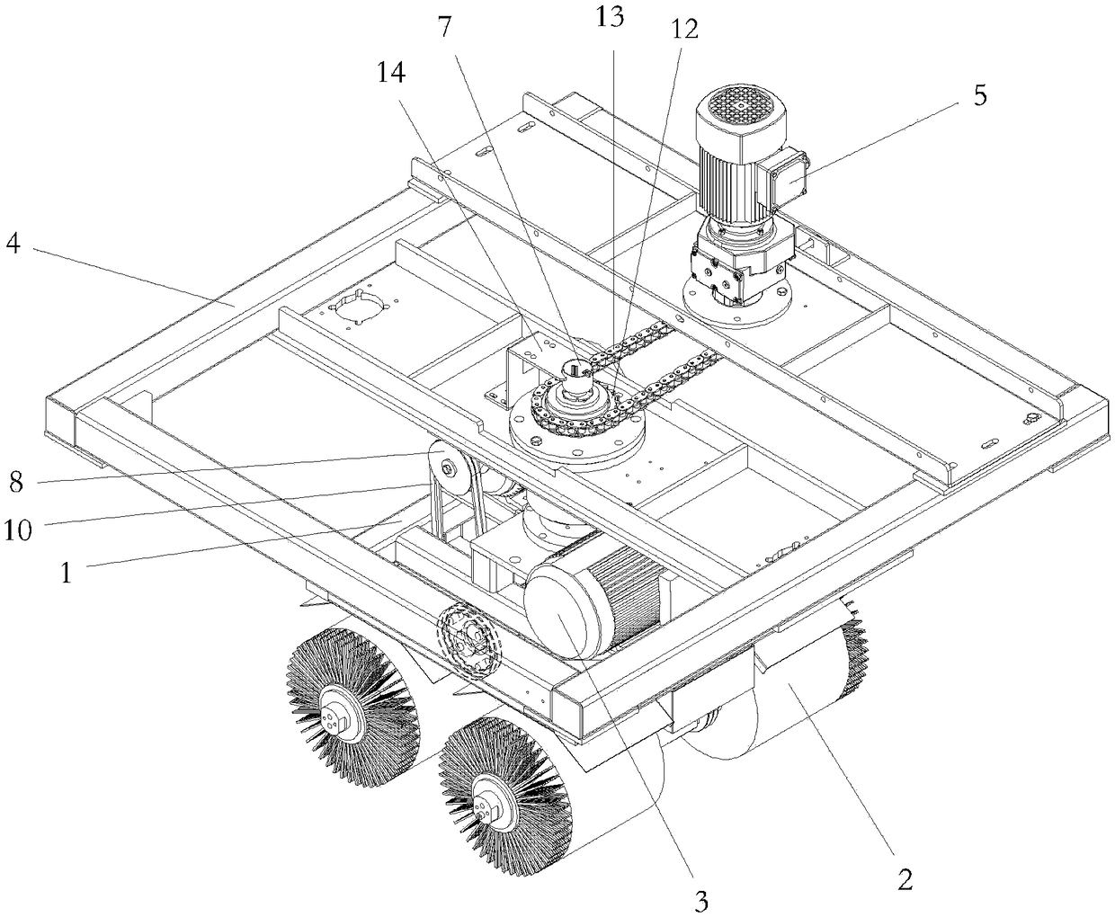
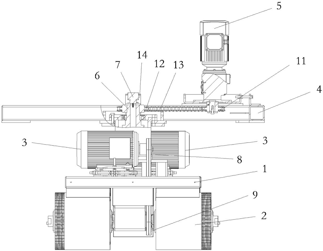
[0020] Shown in conjunction with the accompanying drawings is a specific embodiment of a high-stability rolling brush device of the present invention, including a first bracket 1 and two rolling brushes 2 arranged on the first bracket 1, and on the first bracket 1 Two rotation drive motors 3 are provided, and each rotation drive motor 3 corresponds to each roller brush 2 one by one, and the two rotation drive motors 3 are respectively connected to drive the corresponding roller brush 2 to rotate by rotation transmission mechanism.

[0021] The rotation transmission mechanism includes a driving pulley 8 mounted on the output shaft of the rotation drive motor 3, a driven pulley 9 mounted on the roller brush 2, and a belt connecting the driving pulley 8 and the driven pulley 9. drive belt 10. Since the self-rotation drive motor 3 drives the roller brush 2 to rotate by belt transmission, without the need for a steering gear, it is beneficial to improve the transmission efficiency ...


PUM


Abstract

The invention discloses a high-stability rolling brush device which comprises a first bracket and a rolling brush arranged on the first bracket, wherein a self-rotating driving motor is arranged on the first bracket and the self-rotating driving motor connects and drives the rolling brush to rotate through the self-rotation transmission mechanism; the device also comprises a second bracket and a revolution driving motor arranged on the second bracket, wherein the second bracket is provided with a penetrating revolution shaft with one end fixedly connected with the first bracket, the revolutiondriving motor is connected with the other end of the revolution shaft through a revolution transmission mechanism; the device also comprises a collecting ring, wherein the collecting ring comprises an upper conductive ring fixedly arranged on the second bracket and a lower conductive ring which is connected with the self-rotating driving motor through a lead, the lower conductive ring is arrangedon the revolution shaft, and the upper conductive ring and the lower conductive ring can relatively rotate and are always electrically communicated. The self-rotation part and the revolution part arecompletely separated, the whole structure is simple and clear, the assembly is easier, the problem of circuit entanglement can be avoided, and the transmission efficiency and the operation stabilitycan be improved.

Description

technical field [0001] The invention relates to a high-stability rolling brush device. Background technique [0002] At present, roller brushes are usually used to deburr the workpiece after preliminary processing to ensure that the surface flatness of the workpiece meets the requirements. In the traditional roller brush device, the roller brush is driven by the self-rotation motor to rotate, and the revolution motor is driven to revolve. The roller brush and the self-rotation motor are installed on the bracket, and the steering gear is usually installed on the bracket, and the rotation motor drives the steering gear to rotate and then drives the roller brush to rotate. , the output shaft of the self-rotating motor is coaxially provided with a transmission part installed and fixed on the bracket. The transmission part is driven and rotated by the revolution motor, and by driving the bracket to rotate around the output shaft of the self-rotation motor, the roller brush is fur...

Claims


Application Information

Patent Timeline
Patent Type & Authority Applications(China)
IPC IPC(8): A46B7/10A46B13/02
CPCA46B7/10A46B13/02A46B2200/3086
Inventor 孙雅华
Owner 苏州锃道研磨技术有限公司
Why Eureka
Try Eureka