
Transformer drying equipment

A technology for drying equipment and transformers, used in transformer/inductor cooling, chemical instruments and methods, filtration and separation, etc., can solve problems such as high cost, affecting normal power consumption, and requiring power outage treatment, achieving low cost and improving power supply reliability. Sex, the effect of raising the level

Pending Publication Date: 2019-02-05
YUNCHENG QINGHAI SCI & TECH CO LTD
View PDF0 Cites 0 Cited by
  • Summary
  • Abstract
  • Description
  • Claims
  • Application Information

AI Technical Summary

Problems solved by technology

Therefore, it is necessary to measure the micro-water in the transformer oil. If the content of the micro-water is high to a certain extent, it is necessary to replace the transformer oil or dry the transformer oil. The drying process generally uses a vacuum filter to vaporize and discharge the water in the oil. , to achieve the purpose of drying transformer oil, this method requires power outage processing, affecting normal power consumption
There are also materials that absorb water molecules such as silica gel for drying. These materials need to be replaced after absorbing water, and the cost is high.

Method used


Image

  • Transformer drying equipment
  • Transformer drying equipment

Examples


Embodiment

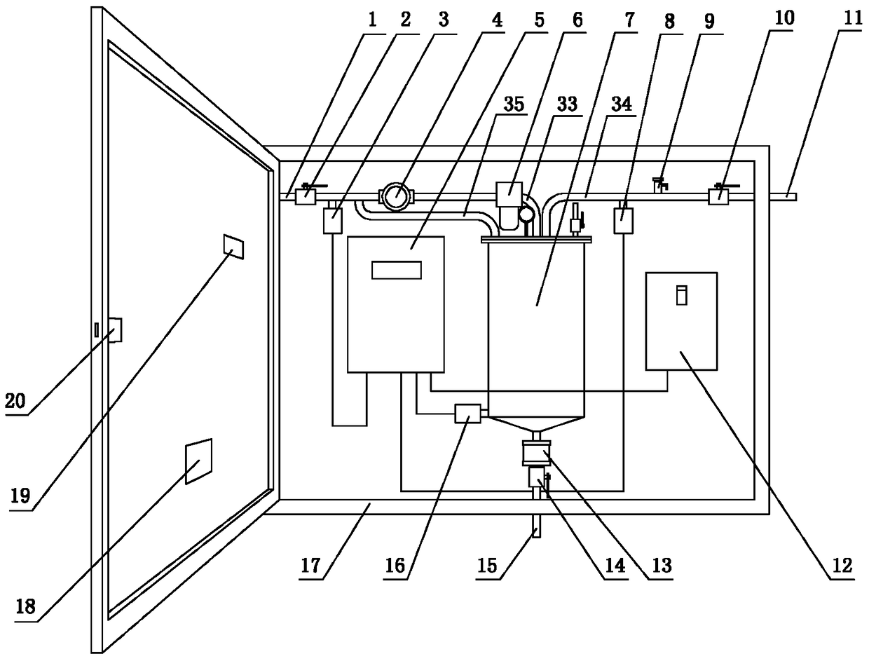
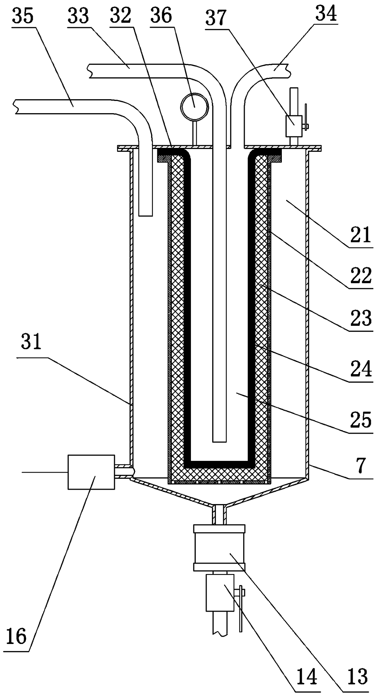
[0013] figure 1 Is a schematic diagram of an embodiment of a transformer drying equipment of the present invention, figure 2 Yes figure 1 Schematic diagram of the internal structure of the middle water removal tank 7; a transformer drying equipment, including the oil inlet pipe 1, the oil inlet valve 2, the oil inlet micro-water sensor 3, the oil pump 4, the micro-water measuring instrument 5, the oil filter 6, and the water removal tank 7. Oil discharge micro-water sensor 8, high-pressure tank discharge valve 9, oil discharge valve 10, oil discharge pipe 11, system control switch 12, water collector 13, water drain valve 14, water discharge pipe 15, water removal tank micro water sensor 16 , Box 17, water collector observation hole 18, micro-water measuring instrument observation hole 19, box door lock 20; one side of the oil inlet pipe 1 can be connected to the bottom of the transformer tank, and the other side of the oil inlet pipe 1 can be connected to the oil inlet valve 2...


PUM


Abstract

Provided is transformer drying equipment. The equipment includes an oil inlet pipe, an oil inlet valve, an oil inlet micro-water sensor, an oil pump, a micro-water gauge, an oil filter, a water removal tank, an oil discharge micro-water sensor, a high-pressure chamber gas relief valve, an oil discharge valve, an oil discharge pipe, a system control switch, a water collector, a water discharge valve, a water discharge pipe, a water removal tank micro-water sensor, a box body, a water collector observation hole, a micro-water gauge observation hole and a box body door lock. The equipment has theadvantages that there is no need to cut off power for disposing transformer oil, normal power usage is not influenced, materials for adsorbing water molecules are not replaced, the cost is low, automatic monitoring is achieved, the transformer oil is always maintained in a qualified state, the safe running level is increased, and the power supply reliability is improved.

Description

Technical field [0001] The invention relates to a transformer drying equipment. Background technique [0002] The transformer used in the power system is filled with insulating transformer oil. Due to thermal expansion and contraction, the transformer is "breathing", that is, air is constantly entering and expelling. Because the air contains moisture, a small amount of moisture (abbreviation: micro water) It enters the transformer oil. The higher the content of water, the lower the insulation degree of the transformer oil. If the insulation degree is low to a certain degree, it will cause internal insulation breakdown and burn the transformer. Therefore, to measure the micro-water in transformer oil, the content of micro-water is high to a certain level, it is necessary to replace the transformer oil or dry the transformer oil. The drying process generally uses a vacuum oil filter to vaporize the moisture in the oil. , To achieve the purpose of drying transformer oil, this metho...

Claims


Application Information

Patent Timeline
Patent Type & Authority Applications(China)
IPC IPC(8): H01F27/14B01D36/00
CPCB01D36/00H01F27/14
Inventor 介贺彤樊沛林赵树海
Owner YUNCHENG QINGHAI SCI & TECH CO LTD
Learn More