Valve rod and valve body assembling machine

A technology of assembly machine and valve body, which is applied in the field of machinery, can solve the problems that only manual tracking and elimination, the valve stem is not positioned, and the assembly cannot be completed, so as to reduce labor costs, equipment costs, and high assembly success rate Effect

Pending Publication Date: 2019-02-05
台州中通智能科技有限公司
View PDF10 Cites 8 Cited by
  • Summary
  • Abstract
  • Description
  • Claims
  • Application Information

AI Technical Summary

Problems solved by technology

[0005] When the above-mentioned valve stem loading device in the ball valve automatic assembly machine is working, the manipulator 3 clamps the valve stem at the 3 places of the cylinder and transports it to the valve body, and the ejector cylinder 3 bumps the manipulator 3, so that the valve stem is installed into the valve body of the valve body. However, the length of the valve stem during assembly is longer than that of the assembly inner hole, and there must be interference during the assembly process. Therefore, when the valve stem is touched and interfered in the assembly valve stem hole, the three lower parts of the manipulator are driven to rotate by bumping. The valve stem is rotated and inserted into the valve stem hole, which is likely to cause the valve stem to interfere and bounce off, resulting in failure and failure to complete the assembly. Moreover, the valve stem and the valve body are not positioned, and the low precision leads to a low assembly success rate.
Through modeling analysis, the success rate of other valve stem assembly machines on the market is basically the same as the above-mentioned valve stem installation device, which is about 92%. Each fault can only be tracked and eliminated manually, and the success rate of 92% is evaluated by the automation standard. , belonging to the basic unqualified category. For example: in a single production, for every 100 products produced, there will be 8 accidents and failures in the equipment, and the normal production can only be resumed after the processing is completed, and the basic output required by the enterprise is 5,000 per day. / set, converted to 400 accidents and 400 downtimes per device per day, which is not feasible

Method used


Image

  • Valve rod and valve body assembling machine
  • Valve rod and valve body assembling machine
  • Valve rod and valve body assembling machine

Examples


Embodiment 1

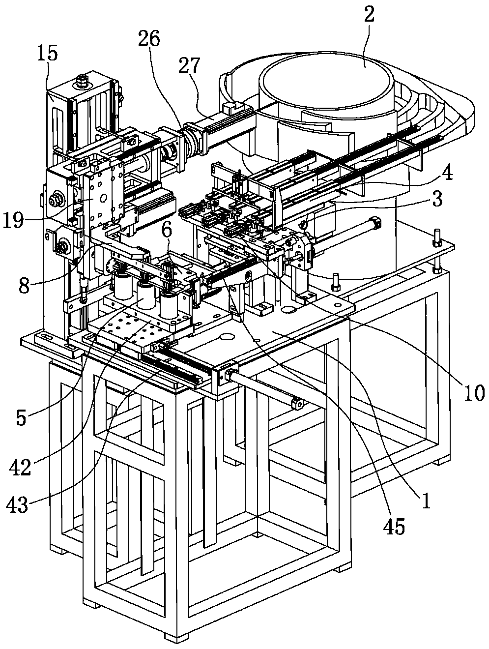
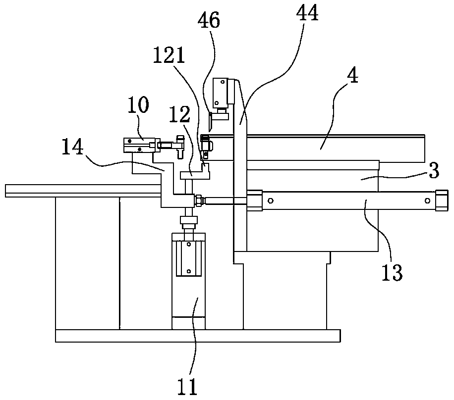
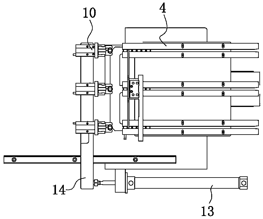
[0034] Such as figure 1 , figure 2 , image 3 , Figure 4 , Figure 6 , Figure 9 and Figure 10 As shown, the valve stem and valve body assembly machine includes a workbench 1, which is provided with a vibrating plate 2 for conveying the valve stem, and a support frame 3 is fixedly connected to the workbench 1, and a vibration plate is fixedly connected to the support frame 3. The feeding slide rail 4 of the tray 2, the workbench 1 is set on the material retaining structure for separating the front valve stem and the inner valve stem in the conveying slide rail, and the workbench 1 is provided with a mold base 5, the mold base 5 has an installation cavity 51 for the valve body to be installed to achieve preliminary positioning. The workbench 1 is provided with a valve stem that transports the valve stem on the delivery slide rail to the mold seat 5 and installs the valve stem into the valve body in the mold seat 5. The valve stem in the hole is loaded into the device, ...

Embodiment 2

[0046] Such as Figure 11 As shown, the structure and principle of this embodiment are basically the same as that of Embodiment 1, the difference is that when the installation cavity 51 of the mold base 5 is used for placing the valve body of the water distributor, the top of the mold base 5 is used for the water distributor. Each valve port of the valve body is exposed and the side gap 52 of the mold base 5 is exposed to each valve stem hole of the water distributor valve body. There are two ejector rods 31 located at both ends of the bottom of the mold base 5 respectively. There are two and corresponding to the ejector rods 31 one by one, the driving part is a cylinder, the cylinder is located at the center of the bottom of the mold base 5 and the piston of the cylinder is fixedly connected under the workbench 1, the cylinder body of the cylinder is fixedly connected to the bottom plate 33, and the two polished rods 34 are located at the two ends of the base plate 33 respect...


PUM


Abstract

The invention provides a valve rod and valve body assembling machine, and belongs to the technical field of machines. The problem that an existing valve rod and valve body assembling machine is low inassembling success rate is solved. The valve rod and valve body assembling machine comprises a workbench, a die base is provided with a notch for a valve rod hole of a valve body to be exposed, a positioning plate is located at the opening part position of an installing cavity for jacking contact of a valve port of the valve body, and the positioning plate is provided with an arranging port. Theworkbench is provided with a supporting structure and a positioning structure, and the die base and/or the positioning plate are/is driven by a displacement mechanism to move. A valve rod arranging device comprises a drive structure, a rotation shaft and a rotation base, the rotation shaft is located at the front end of the drive structure and driven by a rotation mechanism to rotate around the axis of the rotation shaft, the rotation base is fixedly connected to the rotation shaft and fixedly connected with a gas claw, and the distance is formed between the clamping end of the gas claw and the axis of the rotation shaft. After the gas claw clamps the valve rod, the circle center line of the bottom face of the valve rod is basically located at the extension line of the axis of the rotationshaft. The valve rod and valve body assembling machine has the advantages that the assembling precision is high, and the success rate is high.

Description

technical field [0001] The invention belongs to the technical field of machinery and relates to an assembly machine, in particular to a valve stem and valve body assembly machine. Background technique [0002] With the rapid development of social economy, the competitiveness among traditional entity industries must rely on the power of new technologies to break the pattern of traditional industries and then strive for greater profit margins. Among them, improving production efficiency and reducing labor costs are the primary paths. Therefore, If enterprises want to upgrade and transform, they need to start with equipment. The first choice is high-efficiency automation equipment, followed by semi-automated process equipment, which also promotes the heating up of the automation industry. [0003] At present, water separator enterprises and valve enterprises are basically semi-automatic human-machine combination when producing and assembling products. For example, the mature eq...

Claims


Application Information

Patent Timeline
Patent Type & Authority Applications(China)
IPC IPC(8): B23P19/00
CPCB23P19/00B23P19/001B23P19/004B23P19/006B23P19/007
Inventor 许龙钦郑通和柯名官
Owner 台州中通智能科技有限公司
Why Eureka
Try Eureka