LCP material based millimeter-wave antenna system and mobile terminal
A millimeter-wave antenna and mobile terminal technology, which is applied in the direction of antenna, antenna grounding switch structure connection, radiation element structure, etc., can solve the problem of unfavorable overall system performance and integration, deterioration of electrical and mechanical properties, and the number of connector buckles Limited problems, to achieve the effect of reducing electromagnetic leakage, improving stability, and simple structure
- Summary
- Abstract
- Description
- Claims
- Application Information
AI Technical Summary
Problems solved by technology
Method used
Image
Examples
Embodiment 1
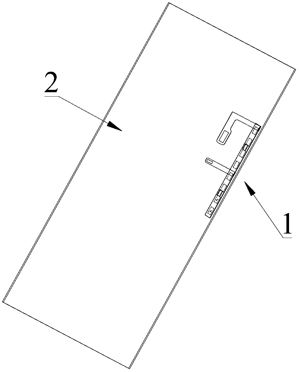
[0034] Please refer to figure 1 and figure 2 , Embodiment 1 of the present invention is:
[0035] Such as figure 1 The shown mobile terminal includes a main body 2 and a millimeter-wave antenna system 1 based on LCP materials, the millimeter-wave antenna system 1 includes an antenna component and a connection component, and the antenna component is arranged near the edge of the main body 2 , the connecting component is electrically connected to the PCB board of the mobile terminal. In this embodiment, the antenna assembly is disposed close to a long side of the main body 2 .
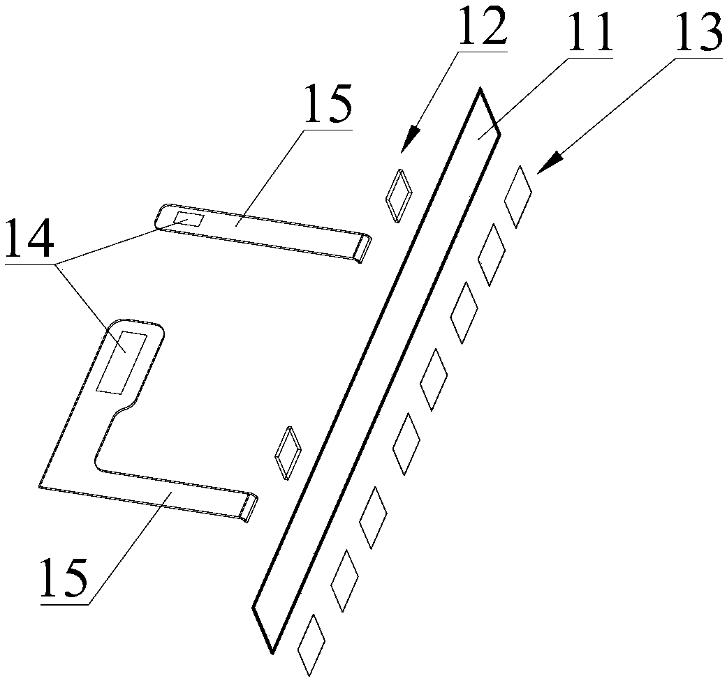
[0036] Such as figure 2 As shown, the antenna assembly includes an antenna layer, a substrate layer 11 and a circuit layer 12, the substrate layer 11 is made of LCP material, and the antenna layer and the circuit layer 12 are arranged opposite to the substrate layer 11. and the antenna layer is electrically connected to the circuit layer 12. Specifically, a metallized via hole can be provided on t...
Embodiment 2
[0039] Please refer to Figure 5 and Figure 6 , the difference between the second embodiment of the present invention and the first embodiment is:
[0040] The number of antenna units 13 is four, the number of circuit chips is one, and the number of connectors 14 is one. The antenna assembly is arranged close to a short side of the main body 2, and the shape of the transmission line 15 in the connection assembly is the same as in Embodiment 1. s difference.
Embodiment 3
[0042] Please refer to Figure 7 and Figure 8 , the difference between the third embodiment of the present invention and the first embodiment is:
[0043]The number of antenna units 13 is four, and the antenna units 13 are circular microstrip patch antennas. The number of circuit chips is one, the number of connectors 14 is one, the antenna assembly is arranged near a short side of the main body 2, and the shape of the transmission line 15 in the connection assembly is different from that of the first embodiment.
[0044] The antenna unit of the present invention can be flexibly selected, not limited to rectangular microstrip patch antenna or circular microstrip patch antenna, including but not limited to monopole antenna, dipole antenna, Yagi Uda antenna, quasi Yagi Uda antenna and pair Periodic antennas, etc. Combinations of some of these antennas, such as a rectangular microstrip patch antenna and a quasi-Yagi-Uda antenna, can also be used. The antenna unit used can rea...
PUM
 Abstract
Description
Claims
Application Information
 - R&D
- Intellectual Property
- Life Sciences
- Materials
- Tech Scout
- Unparalleled Data Quality
- Higher Quality Content
- 60% Fewer Hallucinations
Browse by: Latest US Patents, China's latest patents, Technical Efficacy Thesaurus, Application Domain, Technology Topic, Popular Technical Reports.
© 2025 PatSnap. All rights reserved.Legal|Privacy policy|Modern Slavery Act Transparency Statement|Sitemap|About US| Contact US: help@patsnap.com


