
Field rapid installation device for sensing optical cable, and installation method of device

A technology of sensing optical cable and installation device, which is applied in the direction of optical fiber/cable installation, etc., can solve the problems that the strain transmission performance of sensing optical cable is greatly affected, the scale and length are not completely covered, and it is difficult to quickly lay sensing optical cable. The effect of promoting the use of the area, optimizing the anchoring method, and facilitating construction

Inactive Publication Date: 2019-02-01
CHINA PETROLEUM & CHEM CORP +1
View PDF6 Cites 0 Cited by
  • Summary
  • Abstract
  • Description
  • Claims
  • Application Information

AI Technical Summary

Problems solved by technology

[0003] At present, there have been many project examples at home and abroad that use sensing optical cables to monitor tunnel deformation and pipeline stress, but the monitoring range is relatively small, and most of them are used as engineering demonstration sites, and the scale length is not completely covered. The reason for this phenomenon is There are many aspects, but the installation speed of the sensing optical cable is a problem to be solved urgently in its large-scale application, so it is necessary to provide a new installation process that can effectively improve the installation speed and accuracy to solve such problems
[0004] The existing installation methods of sensing optical cables mainly include pre-embedded, full-adhesive, and fixed-point fixtures. The pre-embedded and full-adhesive installation methods are sensitive to deformation at a small distance. It is easy to reach the limit strain of the sensing optical cable, which will cause damage to the monitoring line
In this case, it is necessary to choose the form of fixed-point laying, and simple physical anchoring has a great influence on the strain transfer performance of the sensing optical cable. The traditional fixture design is complicated, usually divided into male and female, and the construction speed is low. It is not easy to sense the optical cable. Rapid laying of large areas

Method used


Image

  • Field rapid installation device for sensing optical cable, and installation method of device
  • Field rapid installation device for sensing optical cable, and installation method of device
  • Field rapid installation device for sensing optical cable, and installation method of device

Examples


Embodiment Construction

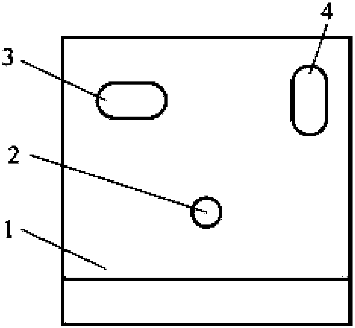
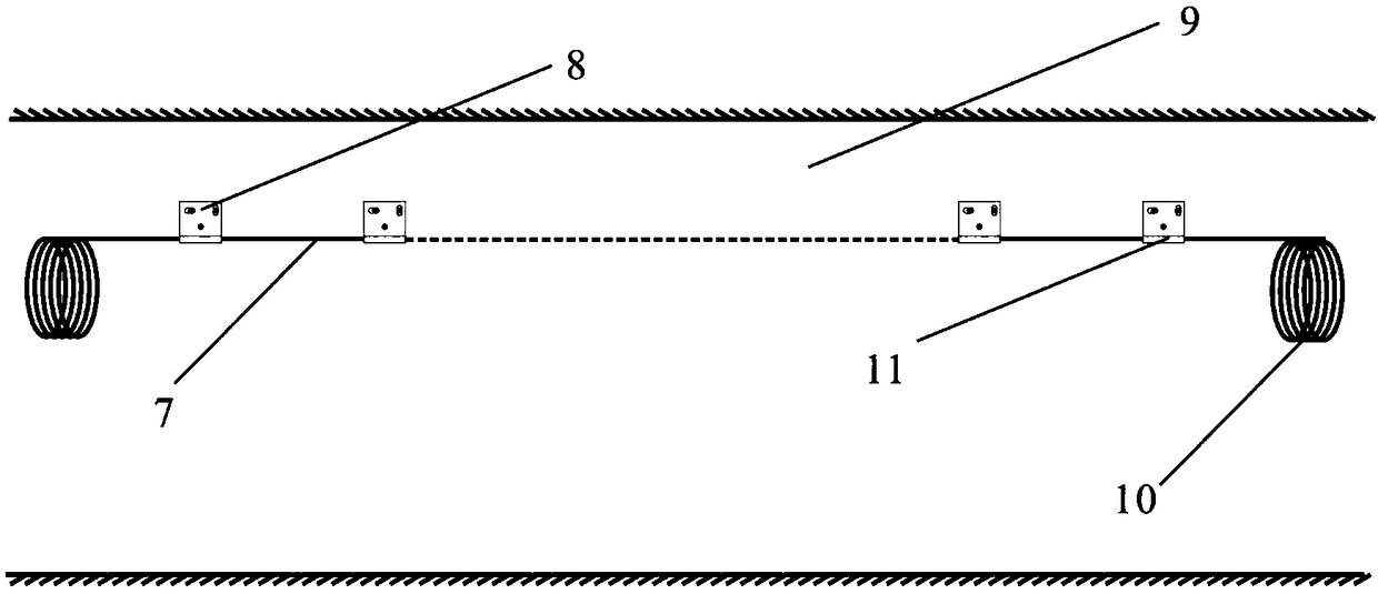
[0027] Such as figure 1 with figure 2 As shown, an on-site quick installation device for sensing optical cables includes a metal panel 1. The metal panel 1 is provided with positioning installation holes 2 and fine-tuning installation holes, respectively, and an optical cable card slot 5 and an optical cable card slot are provided under the metal panel 1. There are several metal bumps in 5 6. Further, the metal panel 1 adopts a high-strength thin-walled steel plate.

[0028] Further, the positioning and mounting hole 2 is provided at the center of the metal panel 1 to play a role of preliminarily fixing the device.

[0029] Further, the fine-tuning mounting holes include a horizontal fine-tuning mounting hole 3 and a longitudinal fine-tuning mounting hole 4. The horizontal fine-tuning mounting hole 3 and the longitudinal fine-tuning mounting hole 4 are respectively provided on the upper part of the metal panel to provide horizontal and vertical fine-tuning spaces respectively. Wh...


PUM


Abstract

The invention provides a field rapid installation device for a sensing optical cable. The device comprises a metal panel; the metal panel is provided with a positioning installation hole and a fine adjustment installation hole; an optical cable slot is formed in the lower part of the metal panel; and a plurality of metal protruding points are arranged in the optical cable slot. The device is smallin size, easy to manufacture, easy to operate, rapid in installation, low in reworking rate, low in cost, small in optical path micro-bending loss and reliable in anchoring effect, and is suitable for installation of sensing optical cables with different sizes, structures and cladding materials; and the sensing optical cable can be effectively fixed on the surfaces of concrete and steel structures.

Description

Technical field: [0001] The invention belongs to the technical field of optical cable installation, and in particular relates to a device for rapid on-site installation of sensor optical cables. Background technique: [0002] Optical fiber sensing technology is a new type of sensing technology that has gradually developed and matured in recent years. Because of its long-distance, corrosion resistance, anti-electromagnetic interference, and good durability, it has been widely used in underground engineering, slope engineering, bridge and tunnel engineering , Pipeline engineering and other large-scale basic engineering fields, and achieved good results, successfully overcoming the disadvantages of traditional sensor measuring points, such as cumbersome layout, low survival rate, and susceptibility to electromagnetic interference. The sensing optical cable in the sensing system is both a sensing element and an optical signal transmission channel, and is an important part of the enti...

Claims


Application Information

Patent Timeline
IPC IPC(8): G02B6/46
CPCG02B6/46
Inventor 李亚平庞平彭云超曹旦夫李平淦邦王克强马凯军侯学瑞王金鹿毛俊辉贾文宝倪广地吴杰张高平赵辉社王萌萌陈昱含庄君张振
Owner CHINA PETROLEUM & CHEM CORP
Learn More