
Well pipe device and method for groundwater layered sampling

A groundwater and well pipe technology, applied in the direction of sampling devices, etc., can solve the problems of complex structure of integrated monitoring well devices, differences in groundwater quality concentration or pollution degree, high requirements for well construction operations, etc., to achieve high practicability and promotion value, layering The sampling method is simple and avoids the effect of large influx

Pending Publication Date: 2019-02-01
JIANGSU PROVINCIAL ACAD OF ENVIRONMENTAL SCI
View PDF0 Cites 2 Cited by
  • Summary
  • Abstract
  • Description
  • Claims
  • Application Information

AI Technical Summary

Problems solved by technology

There are some obvious differences between groundwater pollution and surface water pollution: because pollutants enter the aquifer and move slowly in the aquifer, the pollution often occurs gradually, and it is difficult to detect it in time without special monitoring
[0003] Most of the existing groundwater monitoring well construction devices and sampling methods can only be used to monitor a certain point and a specific aquifer, and the groundwater quality varies in concentration or pollution at different depths at the same location, and mixed water samples cannot be well analyzed. Reflect groundwater conditions
In recent years, in the field of groundwater investigation and monitoring, composite wells or integrated monitoring well devices or other fixed-depth sampling devices have been developed to monitor groundwater at different depths at the same location. However, the construction cost of composite wells is high and integration The structure of the monitoring well device is complex, the requirements for well construction are high, and the cost of well construction is relatively high. The groundwater collected by the fixed-depth sampling device is not a real in-situ groundwater sample. The above devices and methods are greatly affected by the layered sampling of groundwater. limit

Method used


Image

  • Well pipe device and method for groundwater layered sampling
  • Well pipe device and method for groundwater layered sampling
  • Well pipe device and method for groundwater layered sampling

Examples


Embodiment Construction

[0032] The present invention can be better understood from the following examples.

[0033] The structures, proportions, sizes, etc. shown in the accompanying drawings of the description are only used to match the content disclosed in the description, for those who are familiar with the technology to understand and read, and are not used to limit the conditions for the implementation of the present invention, so there is no Technically, any modification of structure, change of proportional relationship or adjustment of size shall still fall within the scope of the technical content disclosed in the present invention without affecting the functions and objectives of the present invention. within the range that can be covered. At the same time, terms such as "upper", "lower", "front", "rear", and "middle" quoted in this specification are only for the convenience of description, and are not used to limit the scope of the present invention. , the change or adjustment of its relat...


PUM


Abstract

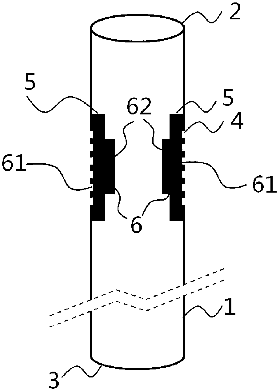
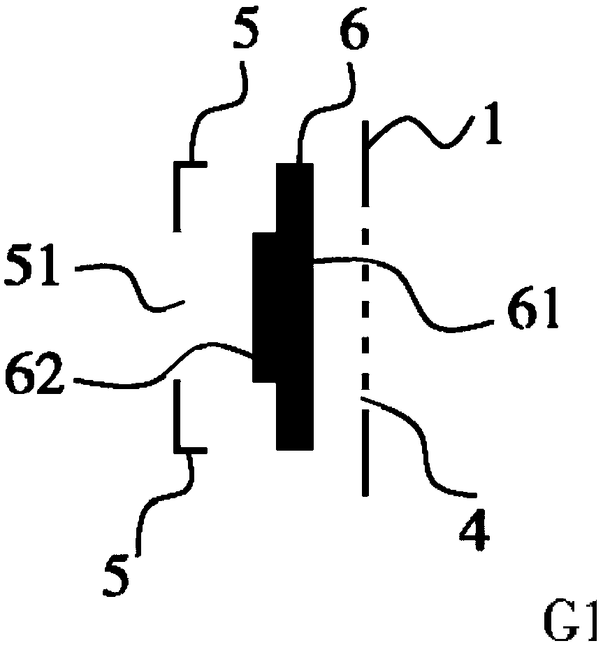
The invention discloses a well pipe device and method for groundwater layered sampling. The device comprises a pipe body formed by connecting more than one well pipe end to end; multiple sets of through sieve holes are formed in the same heights of the side walls of the well pipe; each set of the sieve holes is longitudinally arranged; hollow annular clamping grooves are further formed in the inner wall of the well pipe; the upper arms and the lower arms of the clamping grooves are fixed on the inner wall of the well pipe; the upper arms are located above the sieve holes, and the lower arms are positioned below the sieve holes, so that the sieve holes are surrounded; openings are reserved in the side walls of the clamping grooves; water check valves corresponding to the multiple sets of the sieve holes are arranged in the clamping grooves; and an outer operating rod penetrates through the openings to be clamped with the water check valves, and the operating rod is transversely rotated,so that the water check valves can slide in the clamping grooves, and groundwater with different depths is introduced into the well pipe for sampling.

Description

technical field [0001] The invention belongs to the technical field of environmental protection, and in particular relates to a well pipe device and method for layered sampling of underground water. Background technique [0002] Groundwater pollution is the deterioration of groundwater quality due to human factors. Polluted groundwater is harmful to human health, industrial and agricultural production, and the ecological environment. The strata below the surface are complex, and groundwater flows extremely slowly. Therefore, groundwater pollution has the characteristics of pollution stratification, slow pollution migration, strong pollution concealment, and difficult restoration and treatment. There are some obvious differences between groundwater pollution and surface water pollution: because pollutants enter the aquifer and move slowly in the aquifer, pollution often occurs gradually, and it is difficult to detect it in time without special monitoring. [0003] Most of t...

Claims


Application Information

Patent Timeline
IPC IPC(8): G01N1/16
CPCG01N1/16
Inventor 丁亮王水蔡冰杰曲常胜王栋
Owner JIANGSU PROVINCIAL ACAD OF ENVIRONMENTAL SCI
Learn More