
Coupling heat supply system used for highway service area and heat supply method of coupling heat supply system

A heating system, high-speed service technology, applied in heating systems, household heating, household heating and other directions, can solve problems such as large building heat load, unbalanced underground soil temperature, wind energy instability and intermittent, etc. The effect of good technical and economic effect and high cost

Pending Publication Date: 2019-02-01
HEBEI UNIV OF TECH
View PDF5 Cites 2 Cited by
  • Summary
  • Abstract
  • Description
  • Claims
  • Application Information

AI Technical Summary

Problems solved by technology

[0004] Wind energy is a renewable and clean energy, but this resource is significantly affected by regional and seasonal changes, and there are problems such as intermittency, instability and fluctuation. Wind energy has the defects of instability and intermittency, and soil heat sources can make up for the instability of wind energy alone. Sexual Disadvantages
[0005] In addition, the heat load of buildings in cold northern regions is relatively large, which can easily cause an imbalance of underground soil temperature. This imbalance of soil temperature has a great impact on the efficiency of the entire ground source heat pump system, and it will also destroy the underground ecological balance.

Method used


Image

  • Coupling heat supply system used for highway service area and heat supply method of coupling heat supply system

Examples


Embodiment 1

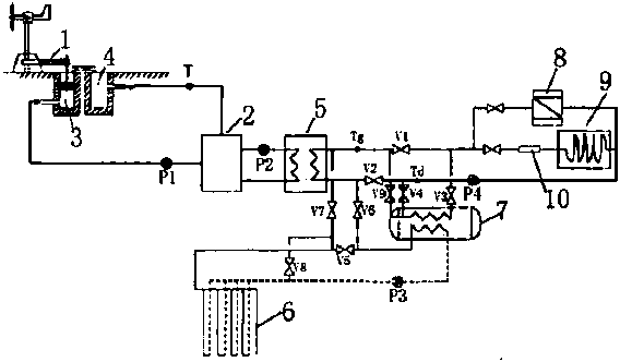
[0031] The coupled heat supply system provided by the present invention is composed of three parts: wind energy heat collection device, soil buried heat exchange device and heat collection device, wherein the wind energy heat collection device and soil buried heat exchange device pass through the air heat exchanger 5 and the plate heat exchanger respectively. Heater 7 realizes heat exchange with heat collecting device.

[0032] The above-mentioned wind energy heat collection device includes a wind turbine unit 1, an air circulation pipeline, an air storage device 2 and a wind energy heat exchange pipeline. During the working process, the air enters the brake 3 of the wind turbine unit 1 through the air pump P1, and is quickly transferred to the wind turbine unit 1 after being heated by the unit. The hot air tank 4 is kept warm, and then flows back to the air storage device 2 through the pipeline, and the heated circulating air flowing back to the air storage device 2 enters the...

Embodiment 2

[0045] In this embodiment, except that the circulating medium of the wind energy heat collection device is replaced with water, other settings are the same as in embodiment 1. Meanwhile, the medium storage device of the wind energy heat collection device is replaced with a heat preservation and moisturizing water tank, and the pump is replaced accordingly.

Embodiment 3

[0047] In this embodiment, except that the circulating medium of the wind energy heat collecting device is replaced with a mixture of water and ethylene glycol, other settings are the same as in embodiment 1, wherein the volume ratio of water to ethylene glycol is 4:1, and the medium of the wind energy heat collecting device The storage was replaced with an insulated hydration tank and the pump was replaced accordingly.


PUM


Abstract

The invention relates to a coupling heat supply system for a highway service area. The coupling heat supply system is composed of three parts including an air energy heat collecting device, a soil buried heat exchange device and a heat collecting device, wherein the air energy heat collecting device and the soil buried heat exchange device achieve heat exchange with the heat collecting device through the heat exchange devices. By means of the coupling heat supply system, a series mode is adopted for achieving running of a ground source heat pump and an air energy combined heat supply system, on one hand, the wind abandoning problem in the wind energy utilization process can be avoided, on the other hand, heat loads obtained in soil can be effectively reduced, balance of a soil layer temperature field is maintained, and the system can be used for well servicing the highway service area.

Description

technical field [0001] The invention belongs to the field of new energy, and in particular relates to a coupled heating system and a heating method for a high-speed service area. Background technique [0002] Energy and environmental issues are major social issues facing all countries in the world today. As the material basis for the development of modern society, energy is closely related to the development of the national economy. Therefore, the research, development and utilization of green new energy have become the common strategic goal of energy construction in all countries in the world. Rational use of energy, improvement of energy utilization and development of new green energy are of great significance to alleviating the energy shortage. [0003] Due to the particularity of their services, high-speed traffic buildings determine that they are within the scope of no municipal supporting facilities, which makes it necessary to build facilities such as heating boilers...

Claims


Application Information

Patent Timeline
IPC IPC(8): F24D15/04F24D19/10
CPCF24D15/04F24D19/10F24D2200/11F24D2200/15Y02B10/40Y02B10/70
Inventor 孔祥飞戎贤矫立超刘平张健新苑广普夏北谦
Owner HEBEI UNIV OF TECH
Learn More