
fire damper

A fire damper and fire-fighting technology, which is applied in the direction of lift valve, valve details, valve device, etc., can solve the problems of poor sealing, easy deformation of fan blades, etc., and achieve the effects of improving sealing, improving heat insulation effect, and improving transmission force

Active Publication Date: 2020-01-07
深圳中鼎工业科技有限公司
View PDF5 Cites 0 Cited by
  • Summary
  • Abstract
  • Description
  • Claims
  • Application Information

AI Technical Summary

Problems solved by technology

[0005] Aiming at the deficiencies of the prior art, the present invention provides a fire damper for fire protection, which has the advantages of being able to carry out secondary sealing and improves the sealing performance of the fire damper, and solves the problem that the existing fire damper only needs to clamp the fan blades to each other. Blocking the smoke and fire once, the fan blades are prone to deformation and poor sealing after a period of time

Method used


Image

  • fire damper
  • fire damper
  • fire damper

Examples


Embodiment Construction

[0034] The following will clearly and completely describe the technical solutions in the embodiments of the present invention with reference to the accompanying drawings in the embodiments of the present invention. Obviously, the described embodiments are only some, not all, embodiments of the present invention. Based on the embodiments of the present invention, all other embodiments obtained by persons of ordinary skill in the art without making creative efforts belong to the protection scope of the present invention.

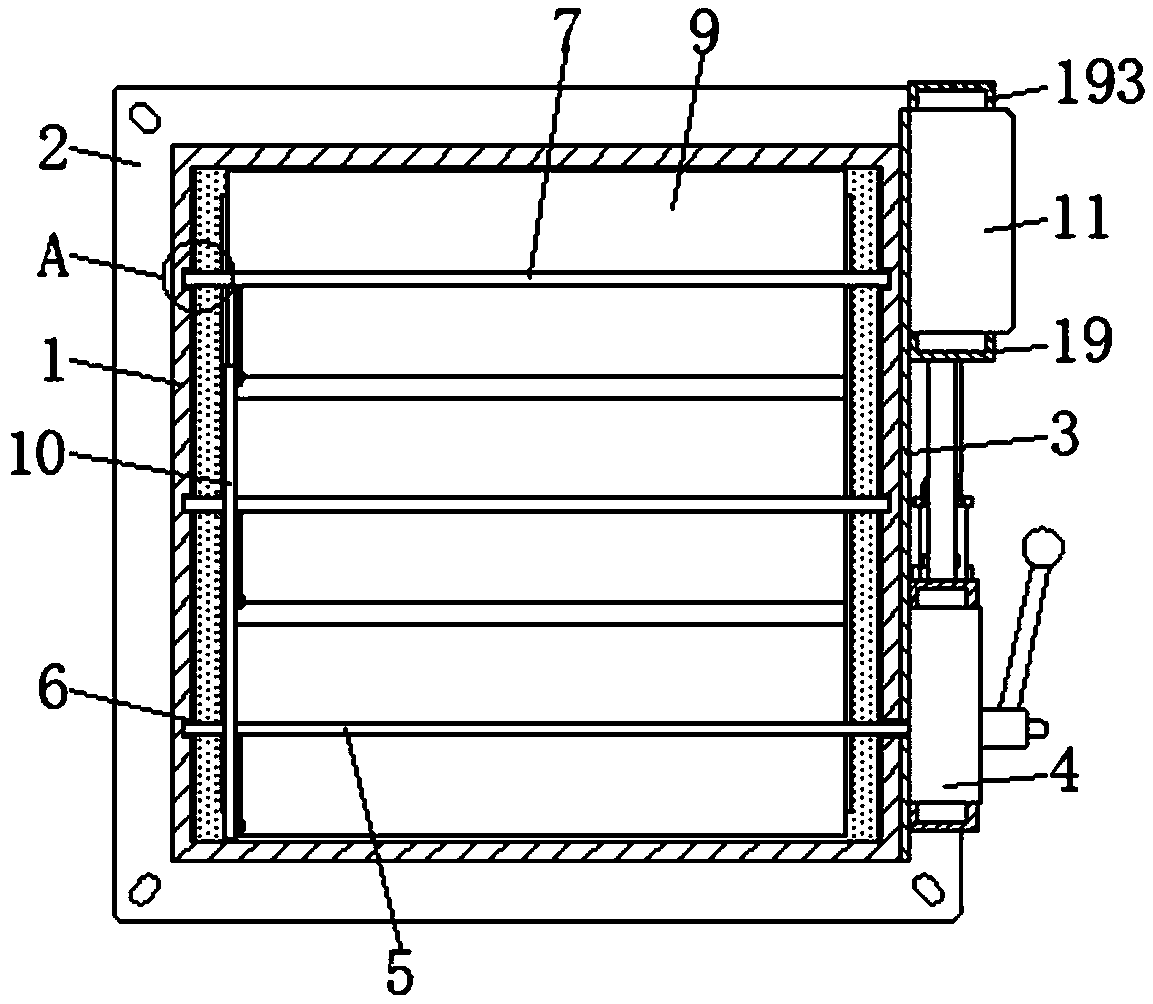
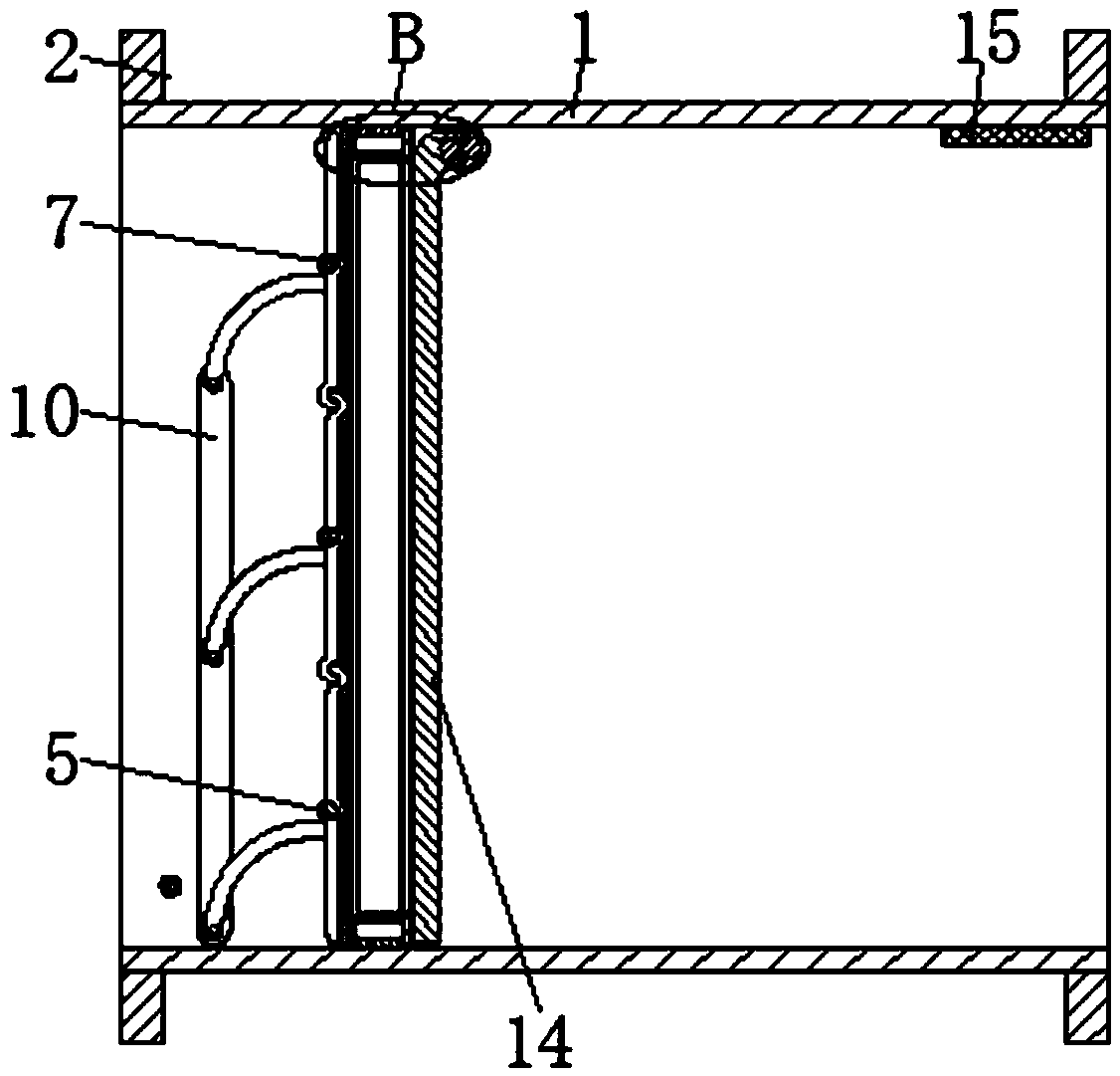
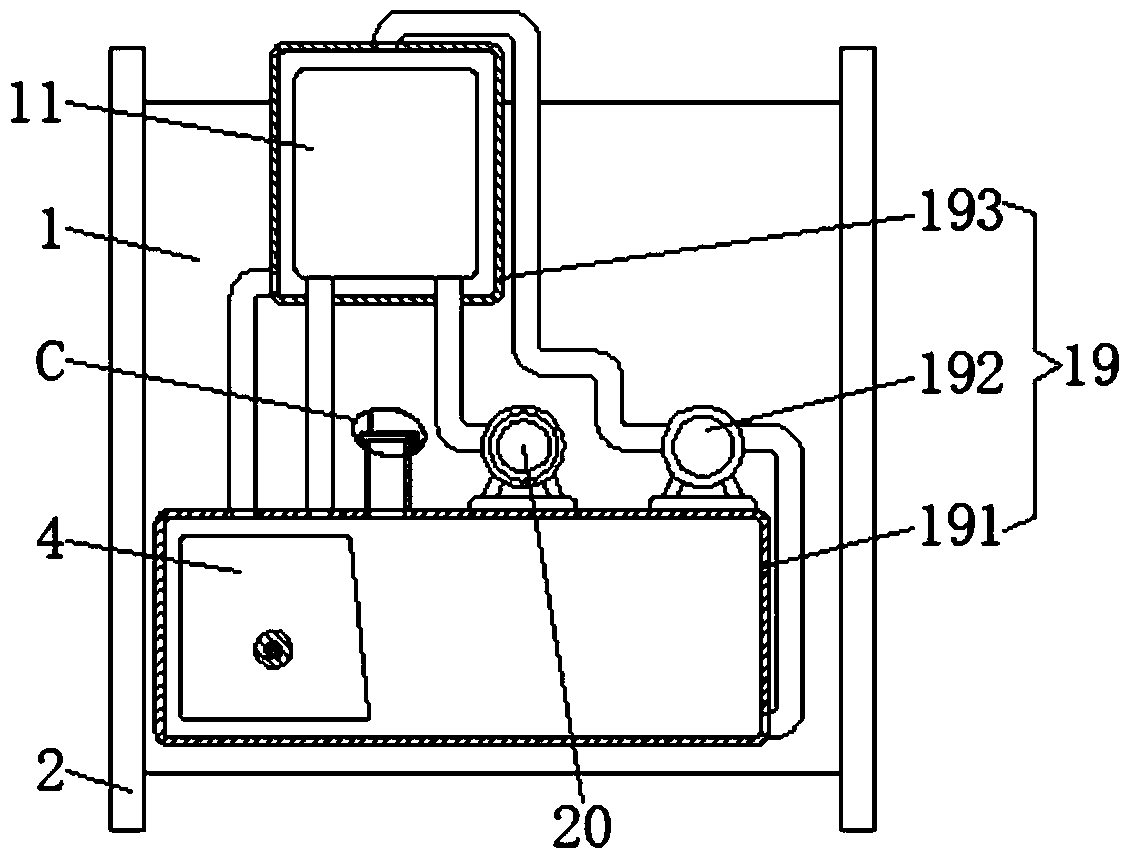
[0035] see Figure 1-8, a fire damper for fire fighting, including a valve body 1, the front and rear ends of the surface of the valve body 1 are fixedly connected with the installation sleeve 2, the right side of the valve body 1 is fixedly connected with the heat insulation board 3, and the bottom of the right side of the heat insulation board 3 The executive device 4 is fixedly connected, and the interior of the actuator 4 is equipped with a transmission ro...


PUM


Abstract

The invention discloses a fireproof valve for fire control. The fireproof valve comprises a valve body. Installing sleeves are fixedly connected to the front end and the rear end of the surface of thevalve body. A heat isolation plate is fixedly connected to the right side of the valve body. The bottom of the right side of the heat isolation plate is fixedly connected with an execution device. Atransmission rod is movably arranged in the execution device. A first circular groove is formed in the bottom of the left side of the inner wall of the valve body. The left end of the transmission rodpenetrates through the first circular groove. A transmission mechanism is used for driving a wind baffle to rotate through a rotation rod, the wind baffle rotates, the interior of the valve body is sealed through a seal mechanism, and accordingly the advantages that secondary sealing can be conducted, and the sealing performance of the fireproof valve is improved are achieved. The problems that an existing fireproof valve conducts one-time stopping on the smoke and the fire behavior only through mutual tight clamping of various fan blades, the phenomenon of deformation is likely to happen tothe fan blades after a period of time, and the sealing performance is poor are solved; and the situation that smoke leakage is likely to happen is avoided, and usage is convenient for people.

Description

technical field [0001] The invention relates to the technical field of fire dampers, in particular to fire dampers for fire protection. Background technique [0002] The fire damper is usually installed in the exhaust duct system. When the temperature of the flue gas reaches 280°C, people have basically evacuated, and the smoke exhaust has no practical significance. At this time, the flue gas is already on fire, and the valve is automatically closed to avoid The fire spreads, the working principle is the temperature control of the highly fusible alloy, and the valve is closed by gravity and the action of the tension spring mechanism. When a fire occurs, the flame invades the air duct, and the high temperature melts the fusible alloy on the valve, or makes the memory alloy Deformation causes the valve to close automatically, and it is used in occasions where air ducts and fire compartments pass through. [0003] However, the existing fire damper only blocks the smoke and fir...

Claims


Application Information

Patent Timeline
Patent Type & Authority Patents(China)
IPC IPC(8): F16K31/53F16K1/22F16K49/00F16K1/32F16K31/70
CPCF16K1/22F16K1/32F16K31/002F16K31/535F16K49/00
Inventor 康毛娣
Owner 深圳中鼎工业科技有限公司
Learn More