
Hydrocyclone desanding device and utilization method thereof

A hydrocyclone and water flow technology, applied in chemical instruments and methods, water/sewage treatment, water/sludge/sewage treatment, etc., can solve problems such as short water inlet channel, wear of pump body, easy deposition of sand particles, etc., to achieve Reasonable structural design, low floor space and high sand removal efficiency

Pending Publication Date: 2019-02-01
BEIJING DRAINAGE EQUIP
View PDF10 Cites 1 Cited by
  • Summary
  • Abstract
  • Description
  • Claims
  • Application Information

AI Technical Summary

Problems solved by technology

[0004] (2) The water inlet channel is too short, and the water inlet flow is in a turbulent state, which affects the wall attachment effect of the desander, resulting in a decrease in the sand removal efficiency of the device;
[0005] (3) Most of them use ordinary pumps to lift sand, which has a high failure rate, serious wear of the pump body, and short service life;
[0006] (4) Intermittent sand discharge, the sand in the sand collection area is easy to deposit, and it will agglomerate after a long time, and it is not easy to be sucked out by the sand discharge pump, which affects the sand discharge effect

Method used


Image

  • Hydrocyclone desanding device and utilization method thereof
  • Hydrocyclone desanding device and utilization method thereof
  • Hydrocyclone desanding device and utilization method thereof

Examples


Embodiment Construction

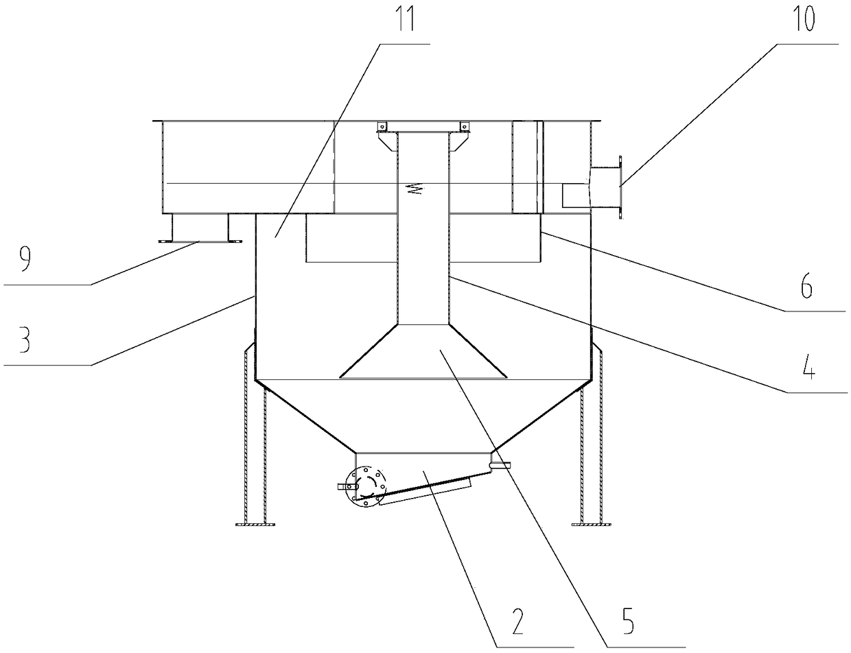
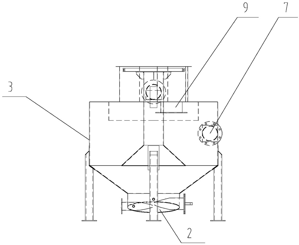
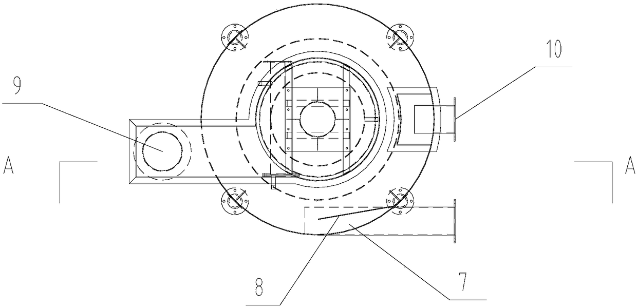
[0031] Attached below Figure 1-4 The hydrocyclone desanding device of the present invention and its usage method are described in detail.

[0032]A hydrocyclone desanding device, the device includes a sand distribution part 1 and a sand bucket part 2; the sand bucket part is arranged below the sand distribution part; the sand bucket part and the sand distribution part are transitionally connected through an annular slope; The sand dividing part includes a cylindrical cavity 3, a central shaft tube 4 that is concentric with the cylindrical cavity and arranged in the cylindrical cavity, and a central cone tube 5 is connected to the bottom of the central shaft tube; it is arranged in the middle and upper part of the cylindrical cavity And concentric with the cylindrical cavity, and the suspension sleeve 6 between the central shaft cylinder and the outer wall of the cylindrical cavity; The bottom plate of the water area is connected, and extends downward into the water in the cy...


PUM

PropertyMeasurementUnit
thicknessaaaaaaaaaa
particle diameteraaaaaaaaaa
densityaaaaaaaaaa

Abstract

A hydrocyclone desanding device comprises a sand separation portion and a sand hopper portion, the sand hopper portion is arranged below the sand separation portion and connected with the same in a transitional manner through an annular slope, the sand separation portion comprises a cylindrical cavity, a central beam barrel, a central cone and a suspension sleeve, the suspension sleeve is an annular plate arranged on a middle-upper portion in the hydrocyclone desanding device, a tangential water inlet is formed in an outer wall of a middle portion of the cylindrical cavity, a flow guide plateis arranged on an inner wall, close to the tangential water inlet, of the cylindrical cavity, an angle ranging from 130 degrees to 180 degrees is formed between the flow guide plate and the tangentialwater inlet, a water outlet and a dreg discharging port are formed in the circumference of an upper portion of the cylindrical cavity, and an annular suspending dreg collection area is formed betweenthe inner wall of the cylindrical cavity and an outer wall of the suspension sleeve. The hydrocyclone desanding device has the advantages of reasonable structural design, convenience in operation andutilization, low operation and maintenance cost, high automaton and intelligentization degrees and the like, and by the aid of the hydrocyclone desanding device, desanding efficiency can be increasedfor sewage treatment, and pollutants such as suspending dregs and grease carried in water can be removed at the same time.

Description

technical field [0001] The invention relates to the technical field of sewage treatment, in particular to a hydrocyclone sand removal device and its use method, which can be widely used in sewage pretreatment sand removal, initial rainwater purification, and sludge pretreatment, and is suitable for new construction, reconstruction and expansion project. Background technique [0002] At present, the commonly used sewage treatment technologies are divided into physical and chemical treatment and biological treatment. Physical and chemical treatment is generally used in sewage pretreatment. Grit chamber is a part of pretreatment, mainly used to remove particles with a size greater than 0.2mm and a density of 2.65t / m 3 Sand to protect subsequent pipelines, valves and other facilities from wear and blockage. However, the sand removal equipment in the traditional grit chamber has the following defects: [0003] (1) The operating load is relatively low, and the organic matter i...

Claims


Application Information

Patent Timeline
Patent Type & Authority Applications(China)
IPC IPC(8): C02F1/38
CPCC02F1/38C02F1/385
Inventor 贺建国李晓辉李艳王宝强秦春禹穆晓东王志锋
Owner BEIJING DRAINAGE EQUIP
Learn More