Airlock with damping mechanism
A shock-absorbing mechanism and air lock technology, which is applied in the field of air locks, can solve problems such as the influence of the service life of the air lock, increase the maintenance cost and procurement cost of the air lock, and achieve the reduction of procurement costs, maintenance costs and procurement costs. Cost, the effect of reducing vibration
- Summary
- Abstract
- Description
- Claims
- Application Information
AI Technical Summary
Problems solved by technology
Method used
Image
Examples
Embodiment 1
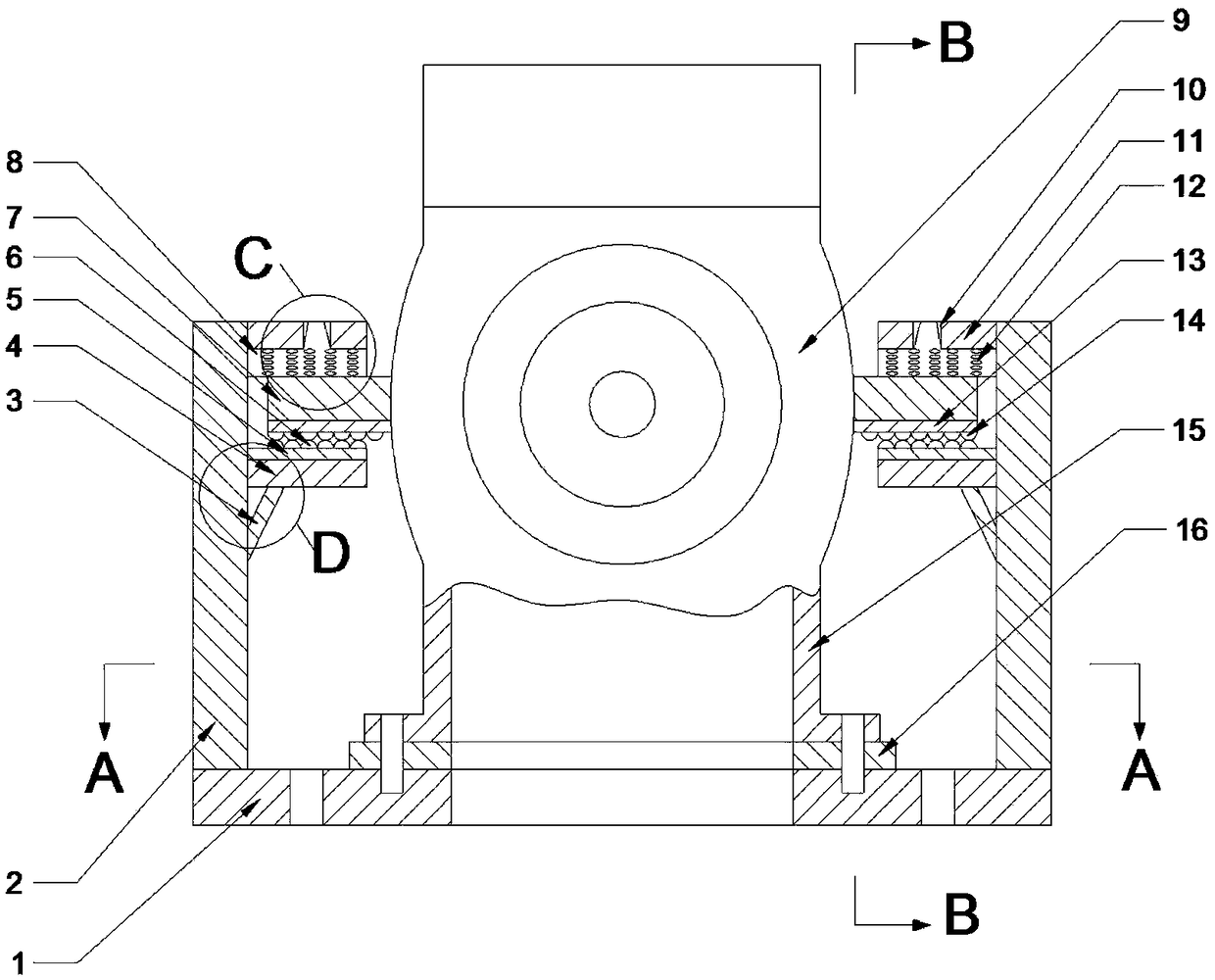
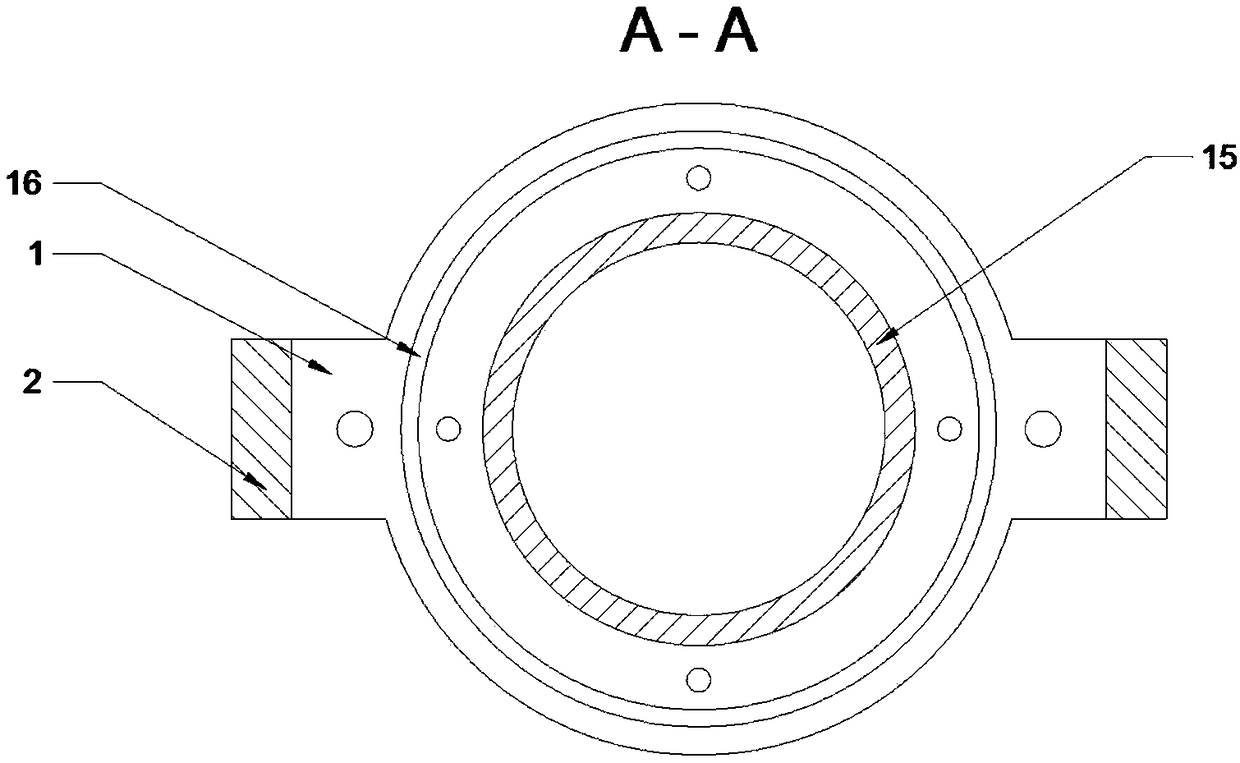
[0038] Such as Figure 1-8As shown, a damper with damping mechanism includes a casing 9 and a discharge port 15, the discharge port 15 is located at the lower end of the casing 9, the bottom surface of the discharge port 15 is connected with a shock absorbing mechanism, and the shock absorbing mechanism includes The bottom plate 1 communicated with the discharge port 15, the two sides of the bottom plate 1 are equipped with vertical vertical plates 2 in the vertical direction, and the upper and top ends of the vertical vertical plates 2 are respectively provided with a lower shock absorber 4 and an upper shock absorber 11 ; Both sides of the casing 9 are respectively provided with shock absorbers 7 in the horizontal direction, and the shock absorbers 7 are located between the lower shock absorber 4 and the upper shock absorber 11 .
[0039] In the present invention, when the blades in the air locker casing 9 rotate and the operation of other equipment causes the air locker to ...
Embodiment 2
[0041] Such as Figure 1-8 As shown, a damper with damping mechanism includes a casing 9 and a discharge port 15, the discharge port 15 is located at the lower end of the casing 9, the bottom surface of the discharge port 15 is connected with a shock absorbing mechanism, and the shock absorbing mechanism includes The bottom plate 1 communicated with the discharge port 15, the two sides of the bottom plate 1 are equipped with vertical vertical plates 2 in the vertical direction, and the upper and top ends of the vertical vertical plates 2 are respectively provided with a lower shock absorber 4 and an upper shock absorber 11 ; Both sides of the casing 9 are respectively provided with shock absorbers 7 in the horizontal direction, and the shock absorbers 7 are located between the lower shock absorber 4 and the upper shock absorber 11 .
[0042] In this embodiment, an air cushion 8 is installed on the bottom surface of the upper damping plate 11, and the air cushion 8 includes an ...
Embodiment 3
[0048] Such as Figure 1-8 As shown, a damper with damping mechanism includes a casing 9 and a discharge port 15, the discharge port 15 is located at the lower end of the casing 9, the bottom surface of the discharge port 15 is connected with a shock absorbing mechanism, and the shock absorbing mechanism includes The bottom plate 1 communicated with the discharge port 15, the two sides of the bottom plate 1 are equipped with vertical vertical plates 2 in the vertical direction, and the upper and top ends of the vertical vertical plates 2 are respectively provided with a lower shock absorber 4 and an upper shock absorber 11 ; Both sides of the casing 9 are respectively provided with shock absorbers 7 in the horizontal direction, and the shock absorbers 7 are located between the lower shock absorber 4 and the upper shock absorber 11 .
[0049] In this embodiment, an upper shock absorbing block 13 is installed on the bottom surface of the shock absorbing plate 7, and an upper sho...
PUM
 Abstract
Description
Claims
Application Information
 - R&D Engineer
- R&D Manager
- IP Professional
- Industry Leading Data Capabilities
- Powerful AI technology
- Patent DNA Extraction
Browse by: Latest US Patents, China's latest patents, Technical Efficacy Thesaurus, Application Domain, Technology Topic, Popular Technical Reports.
© 2024 PatSnap. All rights reserved.Legal|Privacy policy|Modern Slavery Act Transparency Statement|Sitemap|About US| Contact US: help@patsnap.com


