
MOTOR CONTROL DEVICE, PRINTER and control method

A technology of motor control and control method, applied in the direction of motor generator control, printing device, control system, etc., can solve problems such as imbalance

Active Publication Date: 2019-02-01
TOSHIBA TEC KK
View PDF6 Cites 0 Cited by
  • Summary
  • Abstract
  • Description
  • Claims
  • Application Information

AI Technical Summary

Problems solved by technology

Moreover, when the rotational drive is started in a state where the motion remains, there is a risk of loss of balance.

Method used


Image

  • MOTOR CONTROL DEVICE, PRINTER and control method
  • MOTOR CONTROL DEVICE, PRINTER and control method
  • MOTOR CONTROL DEVICE, PRINTER and control method

Examples


Embodiment Construction

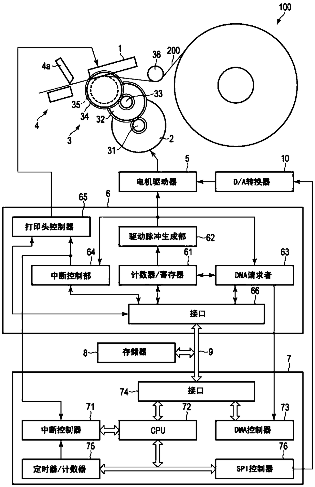
[0048] Hereinafter, an embodiment will be described with reference to the drawings. figure 1 It is a diagram showing the configuration of a part of the mechanism and the block configuration of main circuits of the printer according to the present embodiment. In addition, in this embodiment, a thermal printer is taken as an example for description. Such as figure 1 As shown, the printer 100 includes a thermal print head 1, a stepping motor 2, a conveying mechanism 3, a cutting unit 4, a motor driver 5, a drive control part 6, a printer control part 7, a memory 8, a bus 9 and a D / A (Digital / Analog: digital / analog) converter 10.

[0049] The thermal print head 1 is a type of print head, and prints an arbitrary image on the print medium 200 by discoloring the print medium 200 through heat generated by each of a plurality of heating elements. The thermal print head 1 can change the heating temperature of each of the plurality of heating elements individually and in multiple stage...


PUM


Abstract

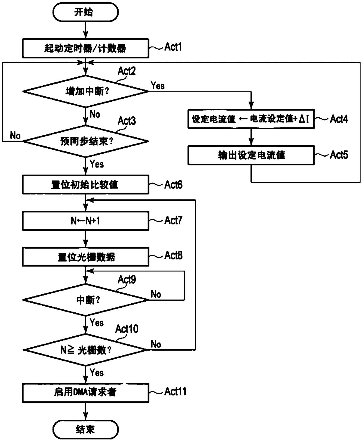
The invention discloses a motor control device, a printer, and a control method, which can reduce the imbalancing risk and shorten the pre-synchronizing period. The motor control device includes a motor driver and a control unit. The motor driver supplies a drive current to a stepping motor. The control unit is configured to control the motor driver to start a supply of the drive current to the stepping motor in response to a start instruction, and increase the drive current to the stepping motor from zero to a predetermined current value stepwise over a predetermined time period.

Description

[0001] This application claims the priority of the Japanese application with the application date of July 25, 2017 and the application number JP2017-143545, and cites the content of the above application, and its disclosure content is incorporated herein by reference in its entirety. technical field [0002] Embodiments of the present invention relate to a motor control device, a printer and a control method. Background technique [0003] Conventionally, there is known a printer that prints a two-dimensional image while performing sub-scanning by moving at least one of the print medium and the print head by a moving mechanism using a print head that simultaneously prints a part of a plurality of rasters constituting an image. Also, the moving mechanism has a stepping motor as a drive source. [0004] The stop position of the stepping motor is not fixed in the non-energized state. Therefore, at the start of the stepping motor, a current of a predetermined current value is su...

Claims


Application Information

Patent Timeline
IPC IPC(8): B41J29/38
CPCB41J29/38B41J11/42B41J19/202H02P8/12B41J23/025B41J25/001
Inventor 高橋隆英
Owner TOSHIBA TEC KK
Learn More