Clamp facilitating PDMS (Polydimethylsiloxane) die releasing and method for preparing PDMS layer thereby

A fixture and demoulding technology, applied in applications, flat products, household appliances, etc., can solve the problems of taking out the PDMS layer, demoulding is easy to break, and the molding effect is not good, so as to achieve enhanced light transmittance, good molding effect, Not easily broken effect

Active Publication Date: 2019-02-01
HARBIN INST OF TECH
View PDF5 Cites 0 Cited by
  • Summary
  • Abstract
  • Description
  • Claims
  • Application Information

AI Technical Summary

Problems solved by technology

[0004] In order to solve the problem that liquid PDMS easily infiltrates between the spacer mold and the bottom plate in the structure of the existing PDMS mold, resulting in poor molding effect, and it is difficult to take out the filled PDMS layer from the mold, and the problem that it is easy to break during the demoulding process, the present invention Provided is a fixture that is beneficial to PDMS demoulding and a method for preparing a PDMS layer using the fixture, and the adopted technical scheme is as follows:

Method used


Image

  • Clamp facilitating PDMS (Polydimethylsiloxane) die releasing and method for preparing PDMS layer thereby
  • Clamp facilitating PDMS (Polydimethylsiloxane) die releasing and method for preparing PDMS layer thereby
  • Clamp facilitating PDMS (Polydimethylsiloxane) die releasing and method for preparing PDMS layer thereby

Examples


Embodiment 1

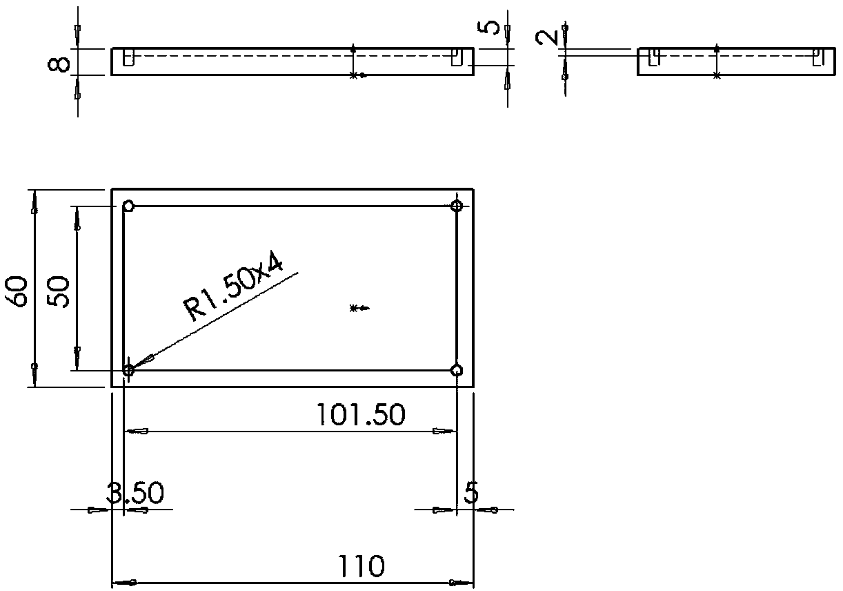
[0032] like Figure 1-6 As shown, the present embodiment provides a fixture that facilitates demoulding of PDMS, the fixture includes a base plate, an intermediate plate and a permanent magnet; the base plate is made of paramagnetic metal; the upper surface of the base plate is provided with a concave Groove, the depth of the groove is greater than the thickness of the middle plate; the groove also extends into the inner wall of the bottom plate with a plurality of demoulding holes evenly arranged along the periphery of the groove, and each of the demoulding holes communicates with the inside of the groove , and each of the demoulding holes runs through the upper surface of the bottom plate and extends to the bottom of the bottom plate; the bottom surface of the groove and can be taken out from the groove; the middle plate is made of ferromagnetic material; the permanent magnet is placed on the back of the bottom plate to attract the middle plate to close the surface of the mi...

Embodiment 2

[0039]This embodiment further limits the middle plate on the basis of embodiment 1 or 2. In this embodiment, the middle plate is provided with a plurality of rectangular holes; the plurality of rectangular holes are regularly arranged in a grid. The rectangular holes are used to make the surface of the cured PDMS layer have a cuboid spacer structure. This solution enables the mold to make the PDMS layer one-time pour molding, without reshaping the structure of the rectangular parallelepiped spacer array on the obtained PDMS layer.

Embodiment 3

[0041] This embodiment further limits the bottom plate on the basis of embodiment 1 or 2. The middle plate in this embodiment is placed in the middle of the groove of the bottom plate, and the distance between the middle plate and the inner wall of the groove is 0.5mm. The margin is used to remove and place the middle plate.


PUM


Abstract

The invention discloses a clamp facilitating PDMS (Polydimethylsiloxane) die releasing and a method for preparing a PDMS layer thereby, and belongs to the technical field of polymer films. The clamp facilitating the PDMS die releasing comprises a bottom plate, an intermediate plate and a permanent magnet, wherein the bottom plate is manufactured through a paramagnetic metal; a groove is formed inthe upper surface of the bottom plate, and the depth of the groove is more than the thickness of the intermediate plate; a plurality of die releasing holes which are uniformly distributed around the groove extend from the groove to the inner wall of the bottom plate; the shape of the intermediate plate fits that of the groove in the bottom plate; the intermediate plate is positioned into the groove in the bottom plate, and the intermediate plate can cover the bottom surface of the groove and can also be moved out from the groove; the intermediate plate is manufactured through a ferromagnetic substance; and the permanent magnet is positioned at the rear part of the bottom plate and is used for attracting the intermediate plate to cling to the bottom surface of the groove in the bottom platethrough the surface. The invention also provides a method for preparing the PDMS layer through the clamp. The clamp is good in forming effect, and hard to break during die releasing; and the clamp isapplicable to PDMS layer manufacturing.

Description

technical field [0001] The invention relates to a jig that facilitates demoulding of PDMS and a method for preparing a PDMS layer by using the jig, belonging to the technical field of polymer films. Background technique [0002] Triboelectric nanogenerator (TENG) is a new type of self-powered device. Its principle is based on triboelectric effect and electrostatic induction effect. It can directly obtain various energy that can cause friction from the environment. The triboelectric effect is a kind of contact electrification effect, which means that after two materials are in contact and friction occurs, due to the different ability of the two materials to gain and lose electrons, the same amount of different charges will be generated on the contact surface, and the material with strong electron ability The surface will have a negative charge, and the surface of the material that has lost electrons will have a positive charge. Polydimethylsiloxane (PDMS) is usually selected...

Claims


Application Information

Patent Timeline
IPC IPC(8): B29C39/02B29C39/36B29C39/26B29C39/22B29L7/00
CPCB29C39/02B29C39/22B29C39/26B29C39/36B29L2007/00
Inventor 张墅野何鹏林铁松许孙武
Owner HARBIN INST OF TECH
Why Eureka
Try Eureka