
Photothermal directionally-controlled liquid drop migration polymerization device and using method thereof

A polymerization device and droplet technology, applied in the field of microfluidics, can solve the problems of poor system stability and easy contamination of reagents, and achieve the effects of stable reaction, convenient operation and high specificity

Active Publication Date: 2019-02-01
CHONGQING UNIV
View PDF5 Cites 8 Cited by
  • Summary
  • Abstract
  • Description
  • Claims
  • Application Information

AI Technical Summary

Problems solved by technology

[0004] However, the use of photosensitive materials to form interfacial tension gradients to manipulate droplets through photochemical reactions has disadvantages such as easy contamination of reagents and poor system stability.

Method used


Image

  • Photothermal directionally-controlled liquid drop migration polymerization device and using method thereof
  • Photothermal directionally-controlled liquid drop migration polymerization device and using method thereof
  • Photothermal directionally-controlled liquid drop migration polymerization device and using method thereof

Examples


Embodiment 1

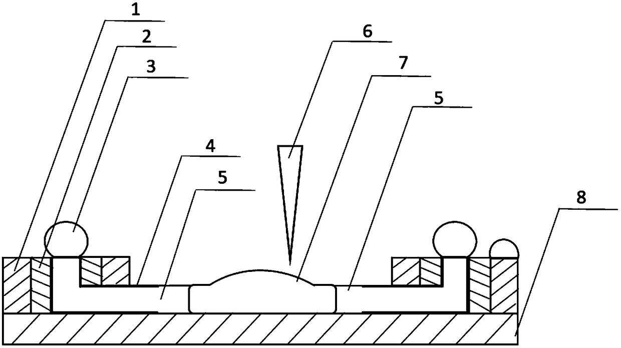
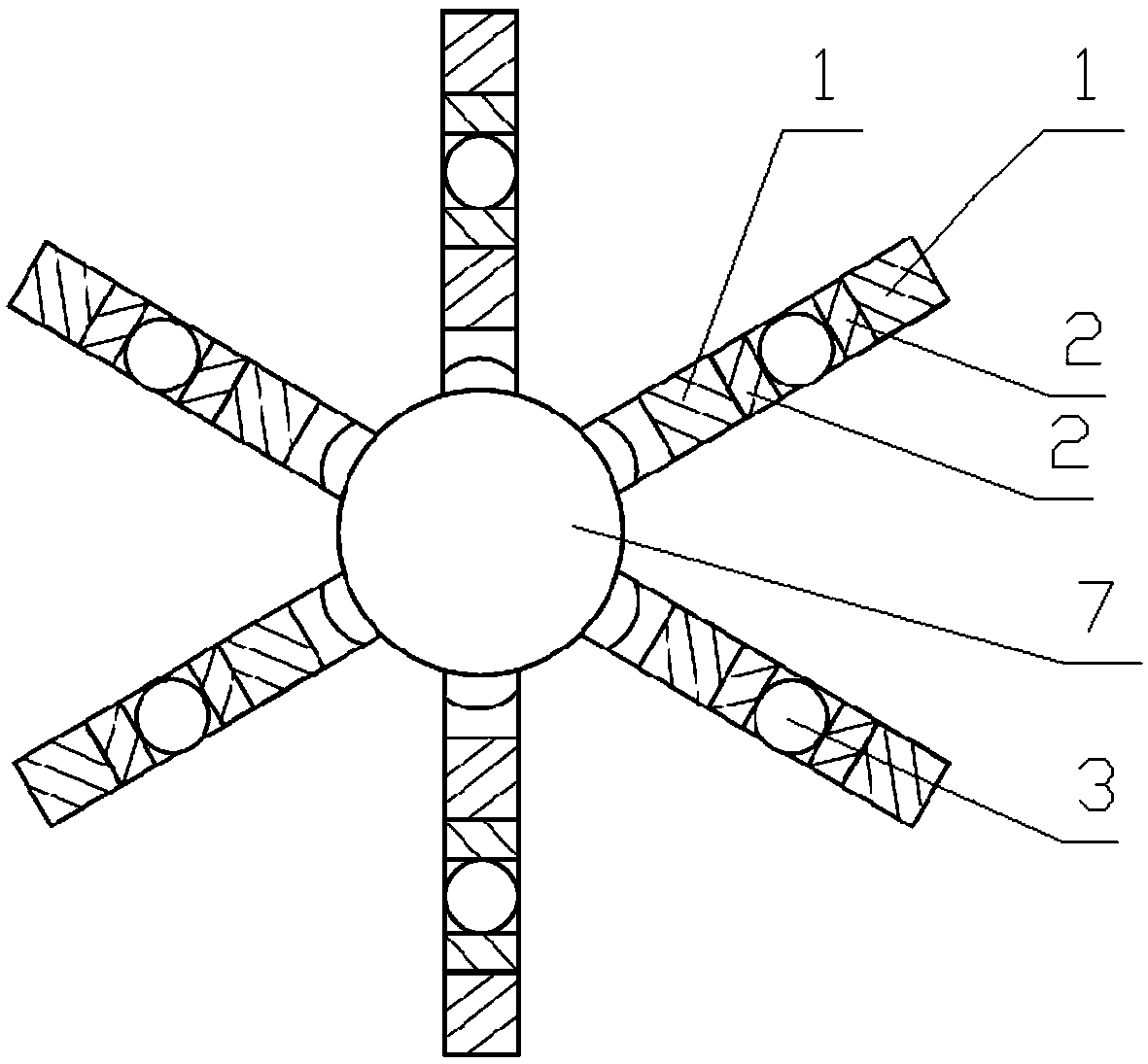
[0036] Such as Figure 1-Figure 2 As shown, the present invention provides a photothermal directional control liquid droplet migration and polymerization device, including a substrate, the central part of the substrate is depressed to form a liquid pool 7, the liquid pool 7 is filled with water, and an infrared laser 6 is arranged above the liquid pool 7. The laser 6 is used to eccentrically heat the water to form steam. The eccentric heating causes the droplets 3 in a specific direction to migrate first, so as to precisely control the migration of the specified droplets 3 and further polymerization reaction. The periphery of the substrate is evenly divided into six cuboids distributed in a divergent shape, and each cuboid is provided with a migration platform. The inside of the substrate is provided with an airflow channel 5 corresponding to the transfer platform for steam flow, which is used to send the steam generated in the liquid pool 7 to the transfer platform, and the a...

Embodiment 2

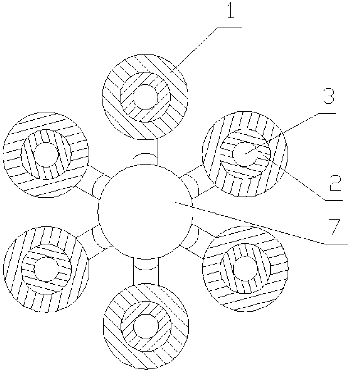
[0051] Such as image 3 As shown, the difference between this embodiment and Embodiment 1 is that the migration platform is cylindrical. Compared with the first embodiment, this embodiment can satisfy the migration of the droplet 3 in different directions without falling off the substrate and sticking impurities, and avoiding errors caused by the contamination of the droplet 3 .

Embodiment 3

[0053] Such as Figure 4 As shown, the difference between this embodiment and the first embodiment is that the substrate is in the shape of a round cake, and multiple transfer platforms are connected to each other to form a whole. Compared with the first embodiment, this embodiment can prevent the droplet 3 from falling into the gap between the transfer platforms, avoid the droplet 3 from falling out of the substrate and stick impurities, and avoid errors.


PUM


Abstract

The invention provides a photothermal directionally-controlled liquid drop migration polymerization device and a using method thereof. The device comprises a substrate, the middle part of the substrate is recessed to form a liquid tank, the liquid tank is filed with a driving liquid, a light heater is arranged above the liquid tank, the light heater is used for eccentrically heating the driving liquid to form steam, at least two migration platforms are arranged around the liquid tank and on the substrate, gas flow channels for the steam to flow, corresponding to the migration platforms one toone, are arranged in the substrate, and are used for delivering the steam generated in the liquid tank to the migration platforms, the diameter of the gas flow channels makes liquid drops stay at theoutlets of the gas flow channels under the action of surface tension, and every migration platform adopts the outlet of the corresponding gas flow channel as a center, and is sequentially provided with a superhydrophobic surface and a hydrophilic surface from inside to outside. The device has the advantages of accuracy in control of the migration of small liquid drops, high stability, compact structure high integration level and quickness in reaction.

Description

technical field [0001] The invention relates to the field of microfluidic technology, in particular to a photothermal directional control liquid droplet migration and polymerization device and its use method. Background technique [0002] In recent years, there have been many studies based on microfluidic chips. Relevant scholars have studied the behavior of droplets on microfluidic chips, especially using light to control the migration of droplets. [0003] Yang et al. studied the use of gradient light formed by an asymmetric light source to irradiate droplets on a chip modified with photosensitive materials to form a wettability gradient and induce droplet motion; Baigl developed another driving method by using visible light or Ultraviolet light irradiates the edge of the droplet containing the photosensitizer (AzoTAB), so that the molecular structure change of the photosensitizer causes Marangoni flow and induces the droplet movement; at the same time, the coaxial light i...

Claims


Application Information

Patent Timeline
Patent Type & Authority Applications(China)
IPC IPC(8): B01L3/00
CPCB01L3/5027B01L3/50273B01L2300/0832B01L2400/0487
Inventor 陈蓉李浩楠朱恂廖强叶丁丁张彪何雪丰朱贤青
Owner CHONGQING UNIV
Learn More