


Quick Research
Generate reliable direction feasibility study reports for your R&D in just a few steps.

Technical Q&A
Discover and master advanced knowledge NOW. Basics, ideas, possibilities, all at once.

Find Solutions
As an expert in R&D theories, this can generate solutions to your technical problems instantly.

Evaluate Feasibility
Analyze your overall solution with one click, know your potential R&D risks in advance.

Monitor Landscape
Get weekly tech updates, stay abreast of the latest tech innovations and key insights.
Omnibearing multi-angle industrial robot
An omni-directional and multi-angle technology, applied in the industrial field, can solve the problems of limited range of motion of the robot, poor flexibility of the robot, and inability to move at will. Effect
- Summary
- Abstract
- Description
- Claims
- Application Information
AI Technical Summary
Problems solved by technology
Method used
Image

Examples
Embodiment 1
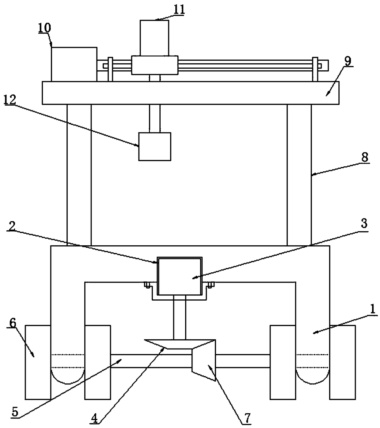
[0028] like Figure 1-5 As shown, the industrial all-round multi-angle robot according to the embodiment of the present invention includes a base 1, the base 1 is an inverted U-shaped structure, and the middle position of the U-shaped groove of the base 1 is provided with a groove 2, so The inside of the groove 2 is provided with a motor 3, the bottom end of the output shaft of the motor 3 is provided with a bevel gear 4, the base 1 is penetrated with a connecting shaft 5, and the connecting shaft 5 is sleeved There are several moving wheels 6 located at the bottom of the base 1, and the middle position of the connecting shaft 5 is sleeved with a bevel gear 2 7 meshed with the bevel gear 1 4, and the top of the base 1 is two A support plate 8 is provided symmetrically on the side, and the top ends of adjacent support plates 8 are connected by a cross plate 9, and the top end of the cross plate 9 is provided with a transmission mechanism 10 and a swing mechanism 11 located on o...
Embodiment 2
[0031] like figure 2 As shown, buffer springs are fixedly connected to the side of the card seat 2 17 close to the sliding seat 18 . The collision force between the sliding seat 18 and the card seat 2 17 is effectively alleviated by the provided buffer spring.
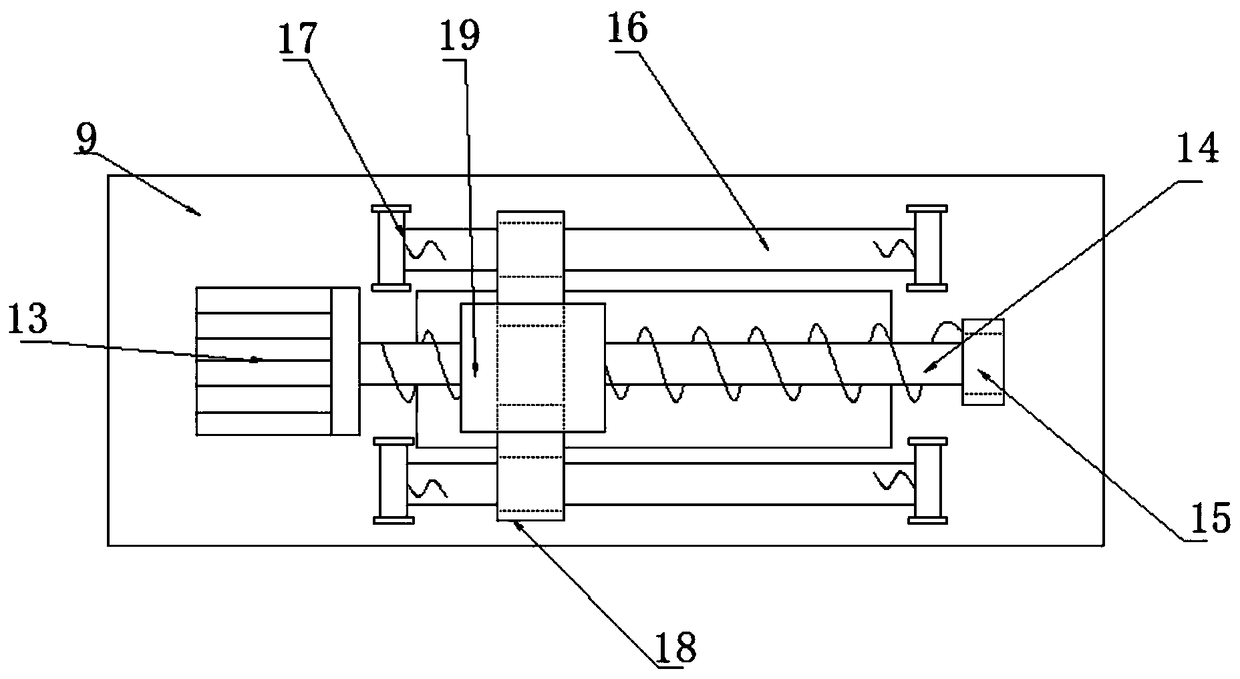
[0032] like figure 2 As shown, the inner middle position of the sliding seat 18 is provided with a threaded hole compatible with the screw rod one 14, and the inner sides of the sliding seat 18 are symmetrically provided with holes matching the sliding rod 16. the chute. Through the provided threaded holes, the movement of the sliding seat 18 is effectively facilitated.
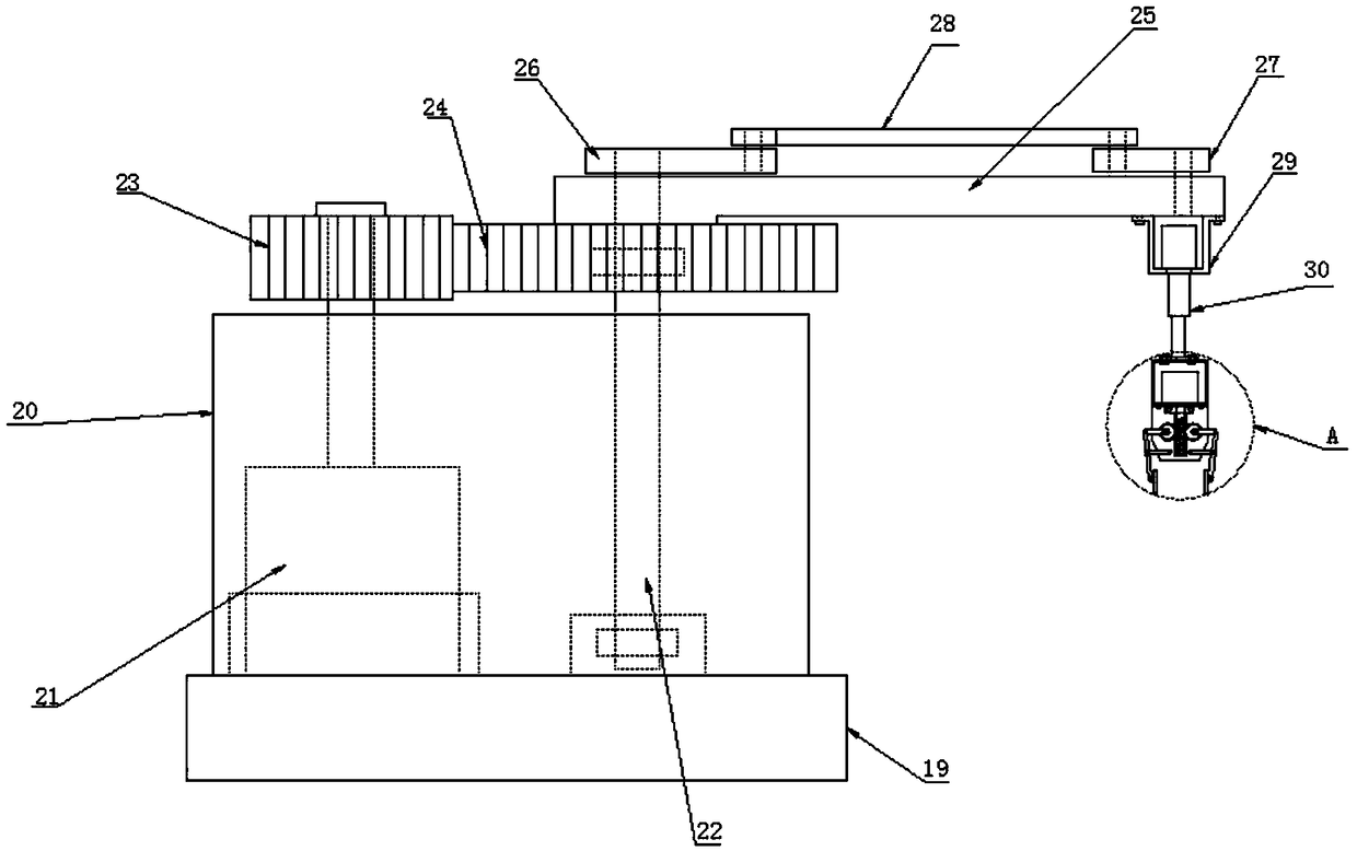
[0033] like image 3 , 4As shown, the swing mechanism 11 includes an installation box 20 arranged on the top of the installation base 19, the inside of the installation box 20 is provided with a motor three 21 and a rotating shaft 22 located on one side of the motor three 21, the The output shaft of the motor three 21 is sleeved with a rotatin...
PUM
 Abstract
Description
Claims
Application Information
 - R&D Engineer
- R&D Manager
- IP Professional
- Industry Leading Data Capabilities
- Powerful AI technology
- Patent DNA Extraction
Browse by: Latest US Patents, China's latest patents, Technical Efficacy Thesaurus, Application Domain, Technology Topic, Popular Technical Reports.
© 2024 PatSnap. All rights reserved.Legal|Privacy policy|Modern Slavery Act Transparency Statement|Sitemap|About US| Contact US: help@patsnap.com