Rapid separation apparatus and separation method of oil-water mixture

A technology of oil-water mixture and separation device, which is applied in separation methods, filtration separation, liquid separation, etc. It can solve the problems of large storage tanks of feed liquid and extraction agent, bulky equipment in the clarification section, and occupation of enterprise working capital, etc., to reduce The storage capacity of material liquid and extractant, easy automatic operation, and the effect of ensuring stable operation

Pending Publication Date: 2019-01-29
CHINA NORTHERN RARE EARTH (GROUP) HIGH TECH CO LTD
View PDF7 Cites 0 Cited by
  • Summary
  • Abstract
  • Description
  • Claims
  • Application Information

AI Technical Summary

Problems solved by technology

[0002] In the field of hydrometallurgy, the commonly used equipment for extraction and separation is a box-type mixing clarifier. After the two phases of the organic phase and the aqueous phase are mixed during the extraction process, it takes a certain period of time for clarification to achieve phase separation, resulting in a large volume of equipment in the clarification section and low production efficiency. Low, and a large amount of storage tanks for feed liquid and extractant, because the feed liquid is expensive, it takes up a lot of working capital of the enterprise
[0003] In the rare earth extraction production process, due to the long-term enrichment of impurity elements, a certain amount of sediment particles will be produced in the extraction tank, and a part of emulsion will also be formed, which will greatly affect the extraction.
Once the sediment and emulsified matter in the extraction tank increase, the emulsified matter in the tank can only be pumped out for treatment, which not only affects the production efficiency, but also causes the loss of raw and auxiliary materials, resulting in an increase in the organic unit consumption during the extraction process and a decrease in the yield of rare earths. , which increases the production cost

Method used


Image

  • Rapid separation apparatus and separation method of oil-water mixture
  • Rapid separation apparatus and separation method of oil-water mixture

Examples


Embodiment Construction

[0027] The following description illustrates specific embodiments of the invention sufficiently to enable those skilled in the art to practice and reproduce it.

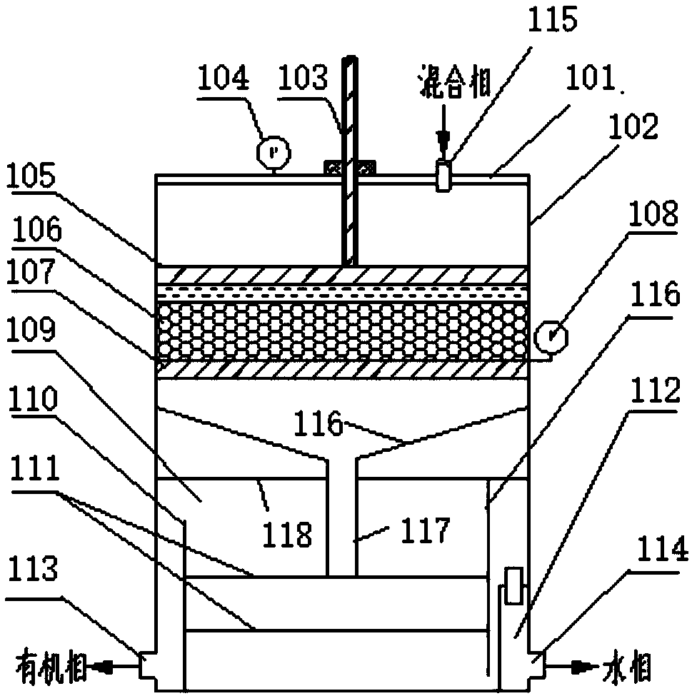
[0028] Such as figure 1 Shown is a schematic structural view of the oil-water separator 1 in the present invention.

[0029] The oil-water mixture rapid separation device includes an oil-water separator 1, which is a closed and pressure-bearing container, including: a top cover 101, a tank body 102, a pressing device 103, a pressure gauge 104, an extrusion plate 105, and a fiber layer 106 , a pressure bearing plate 107 , a pressure sensor 108 , a receiving tank 109 , an overflow plate 110 , a sieve plate 111 , and a water phase adjustment box 112 .

[0030] The top cover 101 and the tank body 102 are made of materials that can withstand 0.5MPa to 1MPa. The top cover 101 is arranged on the top of the tank body 102, and the top cover 101 and the pressing device 103 are connected by threads; the pressure sensor 108 is ...


PUM

PropertyMeasurementUnit
thicknessaaaaaaaaaa
thicknessaaaaaaaaaa

Abstract

The invention discloses rapid separation apparatus of an oil-water mixture. The apparatus comprises an oil-water separator, wherein the oil-water separator comprises a top cover, a tank body, a pressing device, a pressure gauge, an extrusion plate, a fiber layer, a pressure bearing plate, a pressure sensor, a receiving groove, an overflow plate, screen plates and a water phase adjusting box; the top cover is arranged on the top of the tank body, the pressure sensor is arranged on the outer wall of the tank body, the pressure gauge is arranged on the upper part of the top cover, and a mixed phase inlet is formed in the top cover; the pressure bearing plate is fixed on the inner wall of the tank body, and through holes are formed in the pressure bearing plate; the fiber layer is placed on the upper part of the pressure bearing plate, the extrusion plate is arranged on the upper part of the fiber layer, through holes are formed in the extrusion plate, and a probe of the pressure sensor islocated on the pressure bearing plate; and side walls at two sides of the bottom of the tank body are respectively provided with an organic phase outlet and a water phase outlet. The invention further discloses a rapid separation method of the oil-water mixture. According to the invention, an oil-water mixture rapidly passes through a filling layer formed by fiber substances, and rapid separationof the oil-water mixture is realized.

Description

technical field [0001] The invention relates to a rare earth hydrometallurgy technology, in particular to an oil-water mixture rapid separation device and a separation method thereof. Background technique [0002] In the field of hydrometallurgy, the commonly used equipment for extraction and separation is a box-type mixing clarifier. After the two phases of the organic phase and the aqueous phase are mixed during the extraction process, it takes a certain period of time for clarification to achieve phase separation, resulting in a large volume of equipment in the clarification section and low production efficiency. Low, and the amount of feed liquid and extractant storage tank is large, because the feed liquid is expensive, it takes up a lot of working capital of the enterprise. [0003] During the rare earth extraction production process, due to the long-term enrichment of impurity elements, a certain amount of sediment particles will be produced in the extraction tank, an...

Claims


Application Information

Patent Timeline
Patent Type & Authority Applications(China)
IPC IPC(8): B01D17/025B01D36/02
CPCB01D17/0208B01D36/02
Inventor 桑晓云赵治华张国光张文斌刘瑞金张正中李婷婷张永华姜晓丽徐占宇高媛
Owner CHINA NORTHERN RARE EARTH (GROUP) HIGH TECH CO LTD
Why Eureka
Try Eureka