
Microstructure mixer for high-viscosity fluid mixing

A microstructure mixer and fluid mixing technology, which is applied in the direction of fluid mixers, mixers, chemical instruments and methods, etc., can solve problems such as limiting mixing effects, and achieve the effect of reducing flow resistance and quickly and uniformly mixing

Active Publication Date: 2019-01-25
TSINGHUA UNIV
View PDF3 Cites 6 Cited by
  • Summary
  • Abstract
  • Description
  • Claims
  • Application Information

AI Technical Summary

Problems solved by technology

[0003] At present, more mature micro-mixers include interdigitated micro-mixers, Corning heart-shaped mixers, segmentation-polymerization micro-mixers, micro-mesh dispersion mixers, etc. Although these micro-mixers have been realized in many applications High-efficiency mixing of liquid-liquid and gas-liquid, but it is difficult to achieve good results for high-viscosity fluids (>50mPas). The main reason is that the fluids in these micro-mixers need to pass through micron-scale micropores or microchannels. The high flow resistance in these channels limits the mixing effect

Method used


Image

  • Microstructure mixer for high-viscosity fluid mixing
  • Microstructure mixer for high-viscosity fluid mixing
  • Microstructure mixer for high-viscosity fluid mixing

Examples


Embodiment 1

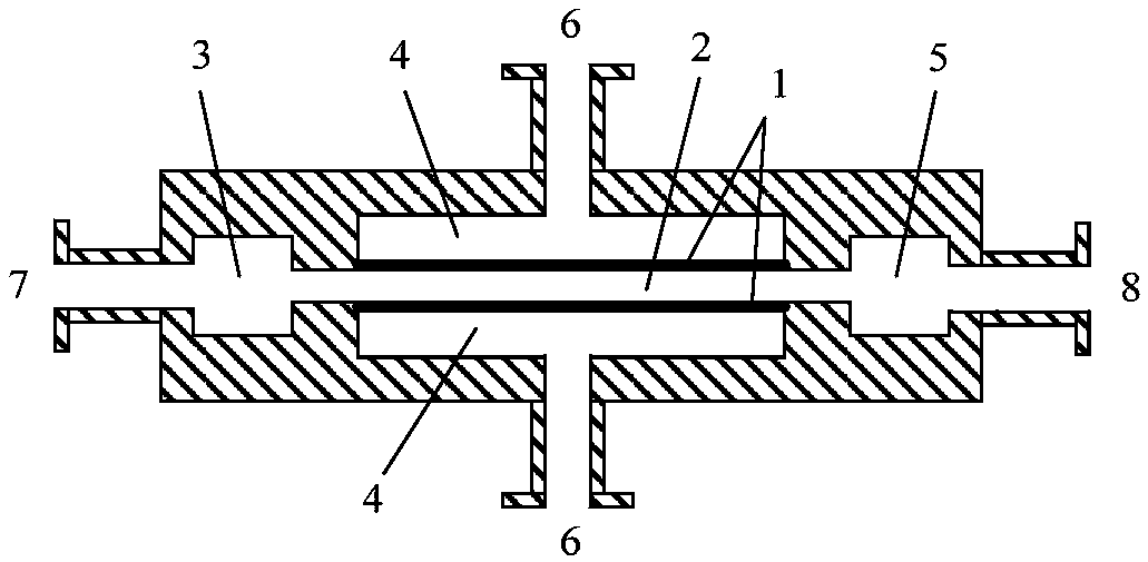
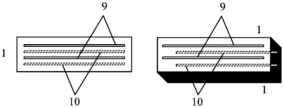
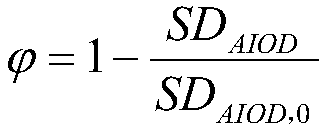
[0020] Use the glycerin aqueous solution (viscosity=100mPas) that contains rhodamine B as mixing medium, contain 1 width 5mm in the micro mixer, the mixing channel of height 1mm, the mixing channel both sides contain 1 group of width 0.4mm, the microgroove of length 10mm, The glycerin solution flow rate that enters from feed inlet (6) is 20mL / min, the glycerol solution flow rate that enters from main feed inlet (7) is 10mL / min, and measurement obtains mixing factor=0.95, and the maximum flow resistance of mixer is 0.1MPa.

Embodiment 2

[0022] Use the glycerol aqueous solution (viscosity=100mPas) that contains rhodamine B as mixing medium, contain 10 width 1mm in the micro mixer, the mixing channel of height 1mm, the mixing channel both sides contain 1 group of width 0.2mm, the microgroove of length 4mm, The glycerin solution flow rate that enters from feed inlet (6) is 100mL / min, the glycerol solution flow rate that enters from main feed inlet (7) is 50mL / min, and measurement obtains mixing factor=0.93, and the maximum flow resistance of mixer is 0.3MPa.

Embodiment 3

[0024] Use the polyvinyl alcohol aqueous solution (viscosity=500mPas) that contains Rhodamine B as the mixing medium, contain 1 width 20mm, the mixing channel of height 4mm in the micro-mixer, there are 2 groups of microgrooves with width 1mm and length 30mm on both sides of the mixing channel , the flow rate of the polyvinyl alcohol solution entering from the feed port (6) is 50mL / min, the flow rate of the polyvinyl alcohol solution entering from the main feed port (7) is 5mL / min, the measurement results in a mixing factor=0.90, and the mixer has the highest Flow resistance 0.1MPa.


PUM


Abstract

The invention belongs to the technical field of chemistry and chemical engineering, and discloses a microstructure mixer for high-viscosity fluid mixing. The microstructure mixer comprises micro dispersion structure components, a mixing passage, a main distribution chamber, a side distribution chamber, a mixed product collecting chamber, a side feeding opening, a main feeding opening and an outlet, wherein (1) the micro dispersion structure components are arranged at the upper and lower sides of the mixing passage, and are plate type mechanical components with longitudinal micro grooves; the micro grooves in the upper side micro dispersion components and the micro grooves in the lower side micro dispersion components are in parallel and alternate arrangement and are not overlapped in a vertical direction; (2) the upper and lower sides of the micro dispersion components are respectively connected with a fluid side distribution chamber; the side distribution chamber is connected with theside feeding opening; (3) the main feeding opening, the main distribution chamber, the mixing passage, the mixed product collecting chamber and the outlet are connected in series. The micro mixer isapplicable to a liquid-liquid mixing process with the viscosity being lower than 500mPa.s.

Description

technical field [0001] The invention belongs to the technical field of chemistry and chemical engineering, and in particular relates to a microstructure mixer for mixing high-viscosity fluids. Background technique [0002] Mixing process is the basic operation process of chemical industry, which is common in chemical process. In continuous reaction and separation systems, passive mixing equipment has the characteristics of simple operation and low energy consumption, and is widely used. However, the internal mixing scale of traditional static mixing devices is generally at the millimeter level, so the mixing efficiency is often relatively low. In recent years, the advent of microstructured mixers (micromixers) has enabled efficient static mixing processes. The micro-structure mixer mainly adopts the basic principle of micro-scale mixing. It disperses or divides two fluids into micron-scale fluid micro-clusters through a micro-dispersion structure, and then completes the mi...

Claims


Application Information

Patent Timeline
Patent Type & Authority Applications(China)
IPC IPC(8): B01F13/00B01F5/06
CPCB01F25/4233B01F25/40B01F33/301B01F33/30
Inventor 王凯骆广生
Owner TSINGHUA UNIV
Learn More