Labor-saving and convenient wire takeup device
A wire take-up, a convenient technology, applied in the field of wire take-up, can solve problems such as inconvenient to carry, laborious to use, not conforming to the habit of using force, etc., to achieve the effect of increasing income, reducing the number of structures, and reducing investment and production costs
- Summary
- Abstract
- Description
- Claims
- Application Information
AI Technical Summary
Problems solved by technology
Method used
Image
Examples
Embodiment 1
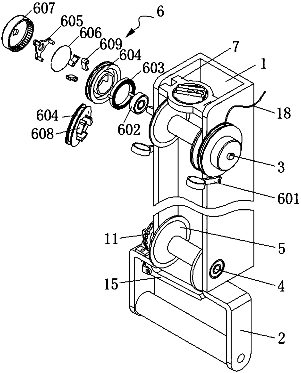
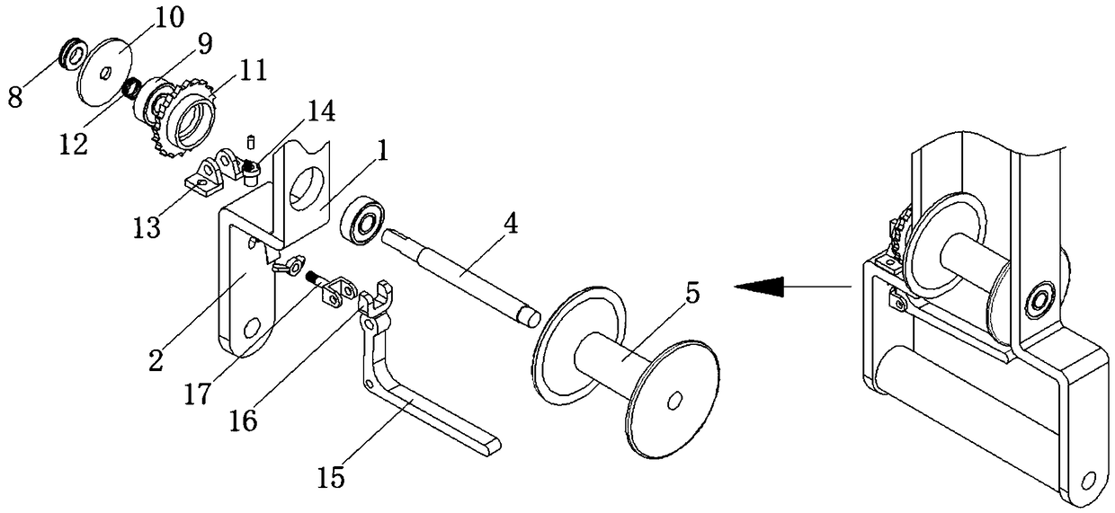
[0037] A labor-saving and convenient kite wire take-up device includes a metal shell 1, a hand-held frame 2, a first rotating shaft 3 and a second rotating shaft 4 are respectively rotatably connected between the two inner side walls of the metal shell 1 through a bearing, the first rotating shaft 3 and the second rotating shaft 3 The outer surface of the two rotating shafts 4 is fixedly sleeved with a take-up reel 5, and the take-up reel 5 is located inside the metal casing 1. Both ends of the first rotating shaft 3 penetrate and extend to both sides of the metal casing 1, and the first rotating shaft 3 The outer circular surfaces of the two ends of the metal shell 1 are flat, and the surface of the metal shell 1 is provided with a wire take-up mechanism 6. The wire take-up mechanism 6 includes a wire guide 601, a second bearing 602, a flat spiral spring 603, a wire wheel 604, and a pawl frame 605 , Spring ring 606 and outer ratchet 607, thread guide 601, second bearing 602, fl...
Embodiment 2
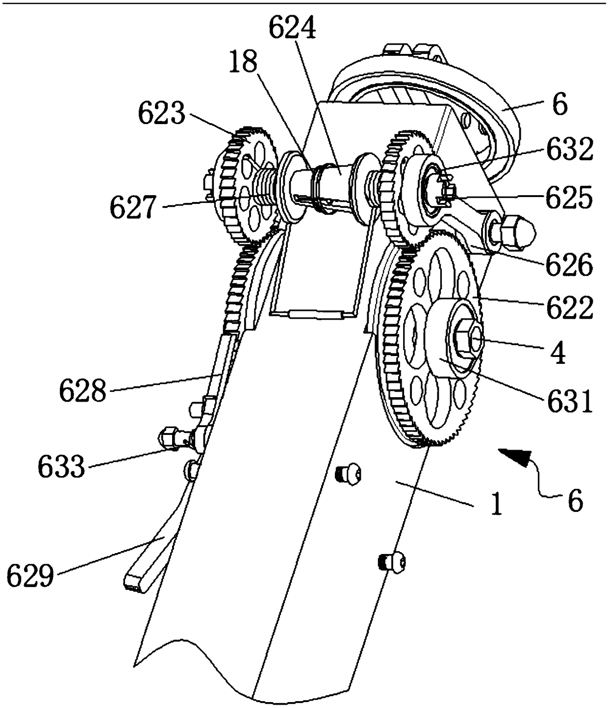
[0042] A labor-saving and convenient kite wire take-up device includes a metal shell 1, a hand-held frame 2, a first rotating shaft 3 and a second rotating shaft 4 are respectively rotatably connected between the two inner side walls of the metal shell 1 through a bearing, the first rotating shaft 3 and the second rotating shaft 3 The outer surface of the two rotating shafts 4 is fixedly sleeved with a take-up reel 5, and the take-up reel 5 is located inside the metal casing 1. Both ends of the first rotating shaft 3 penetrate and extend to both sides of the metal casing 1, and the first rotating shaft 3 The outer round surfaces of the two ends of the metal shell 1 are flat, and the surface of the metal shell 1 is provided with a wire take-up mechanism 6. The wire take-up mechanism 4 includes an outer cover 621, a large ratchet 622, a small ratchet 623, a wire roller 624, a connecting shaft 625, and a swing arm 626 , Large torsion spring 627, long ratchet teeth 628, ratchet cont...
Embodiment 3
[0047] A labor-saving and convenient fishing rod take-up device for fishing boats, comprising a metal shell 1, a hand-held frame 2, and a first rotating shaft 3 and a second rotating shaft 4 are respectively rotatably connected between two inner side walls of the metal shell 1 through a bearing. The first rotating shaft 3 and the outer surface of the second rotating shaft 4 are fixedly sleeved with a take-up reel 5, and the take-up reel 5 is located inside the metal casing 1. Both ends of the first rotating shaft 3 penetrate and extend to both sides of the metal casing 1. The outer circular surfaces of the two ends of a rotating shaft 3 are flat, and the surface of the metal shell 1 is provided with a wire take-up mechanism 6. The wire take-up mechanism 6 includes a wire guide 601, a second bearing 602, a flat spiral spring 603, a wire puller 604, and a ratchet. The number of pawl frame 605, spring ring 606 and outer ratchet 607, thread guide 601, second bearing 602, flat spiral...
PUM
 Abstract
Description
Claims
Application Information
 - Generate Ideas
- Intellectual Property
- Life Sciences
- Materials
- Tech Scout
- Unparalleled Data Quality
- Higher Quality Content
- 60% Fewer Hallucinations
Browse by: Latest US Patents, China's latest patents, Technical Efficacy Thesaurus, Application Domain, Technology Topic, Popular Technical Reports.
© 2025 PatSnap. All rights reserved.Legal|Privacy policy|Modern Slavery Act Transparency Statement|Sitemap|About US| Contact US: help@patsnap.com


