


Quick Research
Generate reliable direction feasibility study reports for your R&D in just a few steps.

Technical Q&A
Discover and master advanced knowledge NOW. Basics, ideas, possibilities, all at once.

Find Solutions
As an expert in R&D theories, this can generate solutions to your technical problems instantly.

Evaluate Feasibility
Analyze your overall solution with one click, know your potential R&D risks in advance.

Monitor Landscape
Get weekly tech updates, stay abreast of the latest tech innovations and key insights.
Salted fish automatic processing device
An automatic processing and salting fish technology, which is applied in fish processing, slaughtering, food science, etc., can solve the problem of destroying the integrity of fish meat, and achieve the effects of avoiding damage, saving time and improving work efficiency
- Summary
- Abstract
- Description
- Claims
- Application Information
AI Technical Summary
Problems solved by technology
Method used
Image

Examples
specific Embodiment approach 1
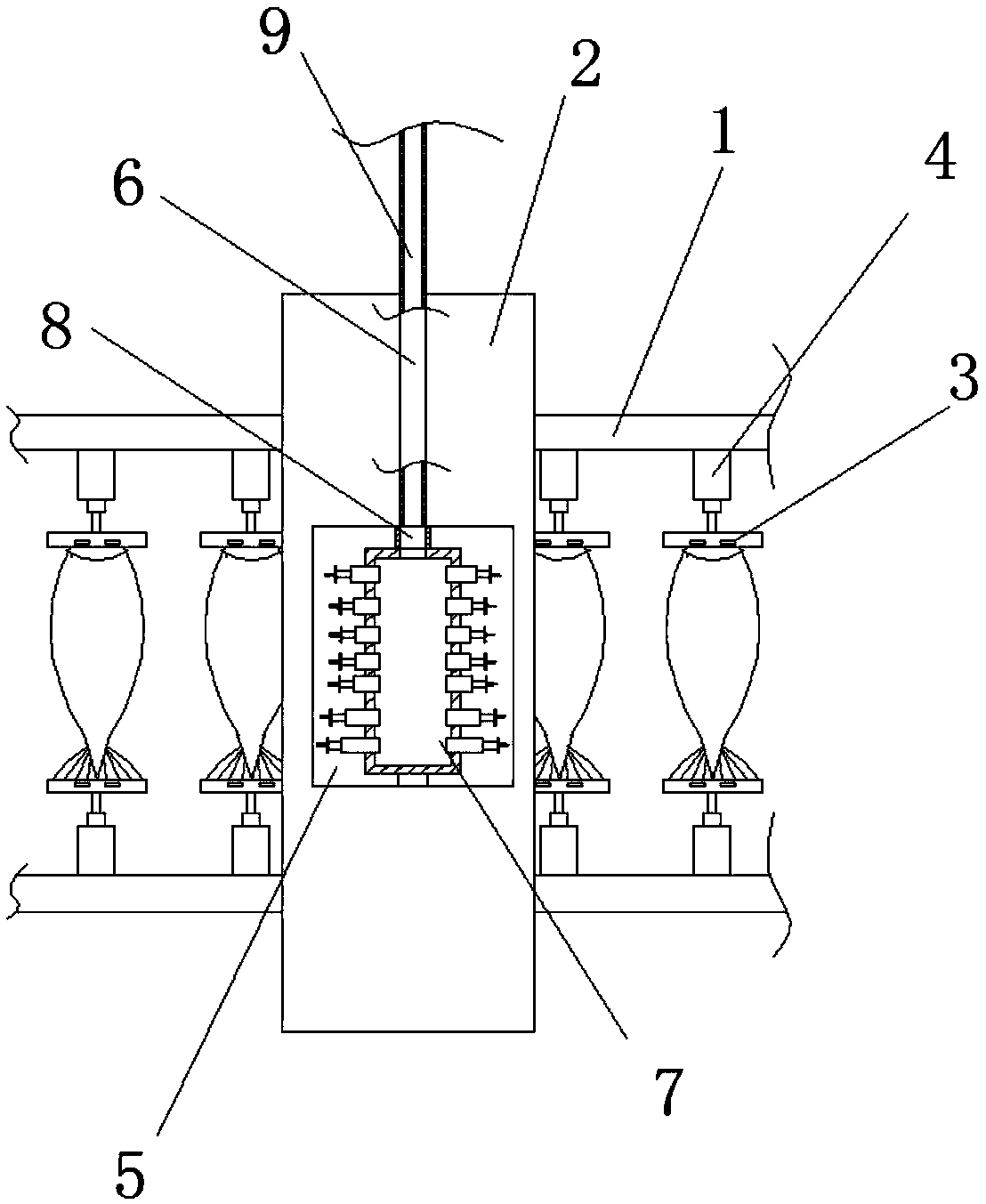
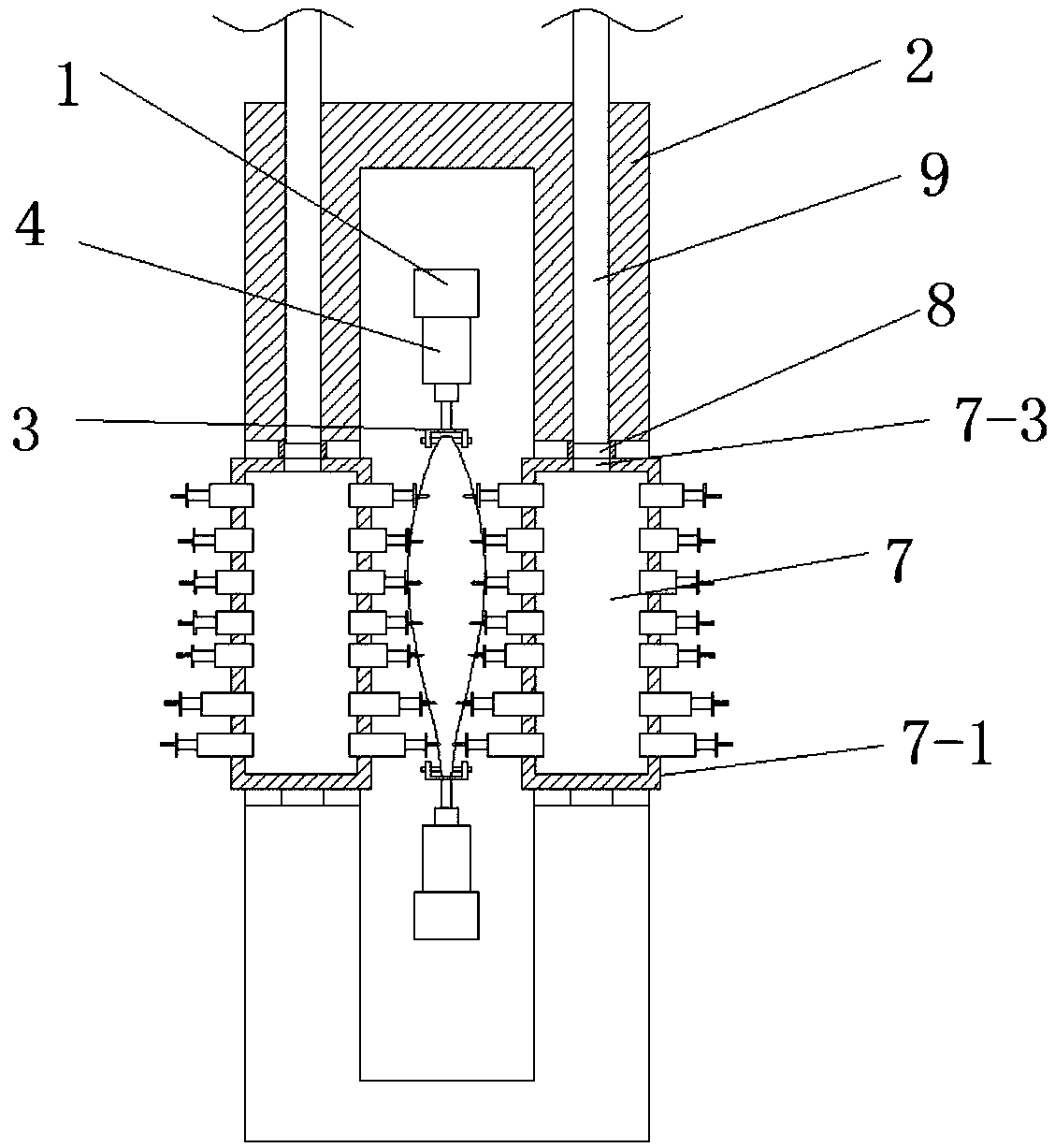
[0029] Such as Figure 1 to Figure 5 As shown, a salted fish automatic processing device disclosed in this embodiment includes a transmission device 1, a fixed frame 2, a fixed clamp 3, a cylinder 4, an injection device 7, a hollow shaft 8 and an infusion tube 9; two transmission devices 1 are parallel Set in the fixed frame 2, multiple sets of fixed clips 3 are symmetrically arranged on two parallel transmission devices 1 through the cylinder 4, the two side walls of the fixed frame 2 are symmetrically opened with a rectangular groove 5, and the upper end of the rectangular groove 5 is opened with a through cavity 6, The upper and lower ends of the injection device 7 are respectively arranged in the rectangular groove 5 through the hollow rotating shaft 8 and the rotating shaft. One end of the infusion tube 9 is connected with the high-pressure water pump, and the other end is arranged in the hollow rotating shaft 8 through the cavity 6;
[0030] Such as figure 1 and 2 As s...
specific Embodiment approach 2
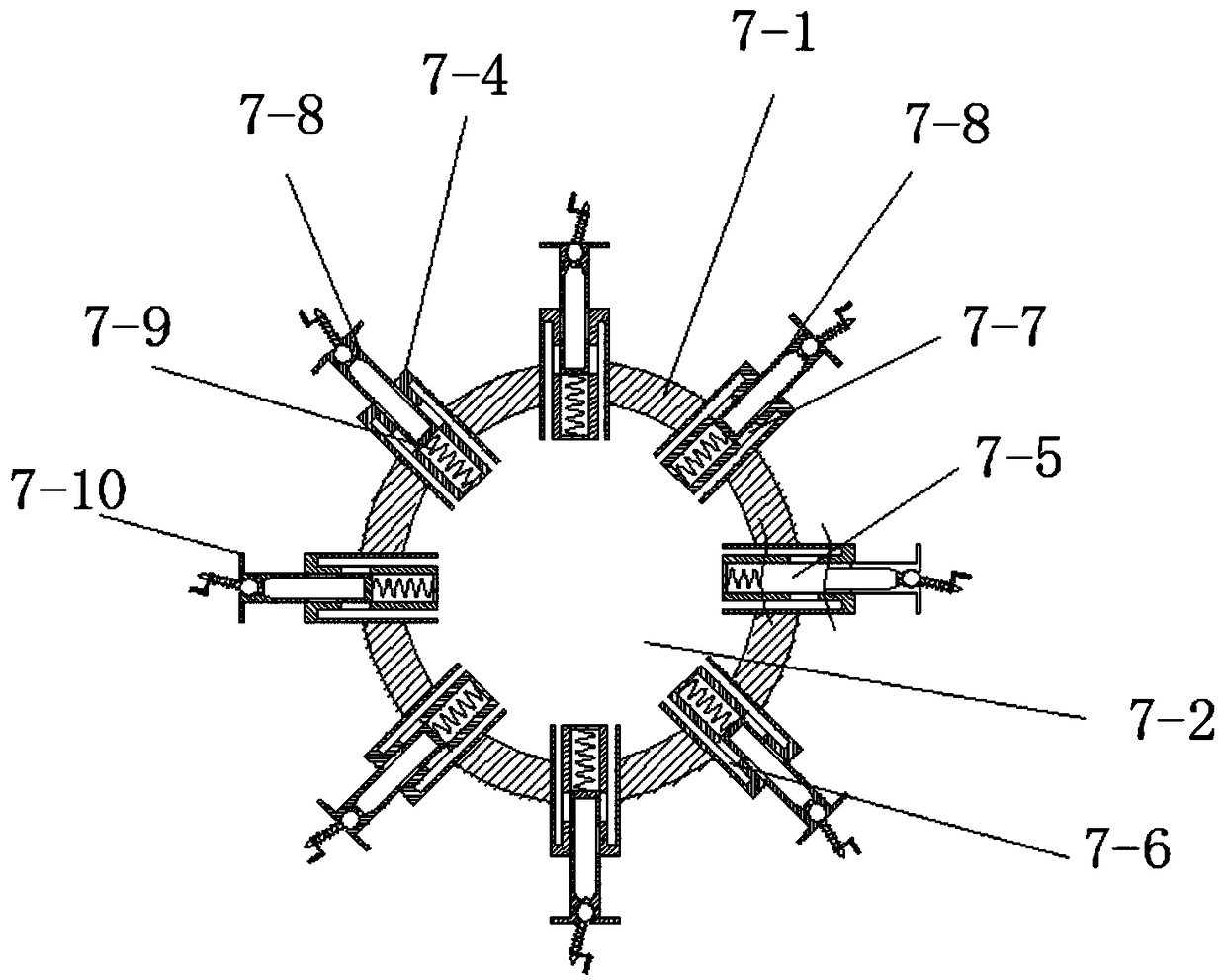
[0036] combine Figure 6 and 7 As shown, this embodiment is based on the first embodiment, the difference is that the elastic member 7-8-10 includes a connecting piece 7-8-11, a pressing rod 7-8-12, and a pressing roller 7-8 -13, the second pressure spring 7-8-14, the fixed rod 7-8-15 and the limit protrusion 7-8-16; one end of the connecting piece 7-8-11 and the limit ring 7-8-8 The side walls are connected, and one end of the symmetrically arranged pressure rod 7-8-12 is connected through the pressure roller 7-8-13, and the other end passes through the second pressure spring 7-8-14 and the connecting piece 7-8-11 in sequence, And be connected by fixed rod 7-8-15, one end of the second pressure spring 7-8-14 links to each other with connecting piece 7-8-11, and the other end is connected with the limit protrusion on the side wall of pressure rod 7-8-12 From 7-8-16 connected;
[0037] The changing process of the power of elastic member 7-8-10, the pushing force of beginning...
specific Embodiment approach 3
[0038] combine Figure 4 and 5 , this embodiment is based on the first embodiment, the difference is that the elastic member 7-8-10 includes a connecting piece 7-8-11, a pressing rod 7-8-12, and a pressing roller 7-8-13 , the second pressure spring 7-8-14, the fixed rod 7-8-15 and the limit protrusion 7-8-16; one end of the connecting piece 7-8-11 and the side wall of the limit ring 7-8-8 Connected, one end of the symmetrically arranged pressure rod 7-8-12 is connected through the pressure roller 7-8-13, and the other end passes through the second pressure spring 7-8-14 and the connecting piece 7-8-11 in turn, and passes through The fixed rod 7-8-15 is connected, and one end of the second pressure spring 7-8-14 is connected with the connecting piece 7-8-11, and the other end is connected with the limit protrusion 7 on the side wall of the pressure rod 7-8-12 -8-16 connected.
[0039] Further, the distance from the highest point of the pressure roller 7-8-13 to the connectin...
PUM
 Abstract
Description
Claims
Application Information
 - R&D Engineer
- R&D Manager
- IP Professional
- Industry Leading Data Capabilities
- Powerful AI technology
- Patent DNA Extraction
Browse by: Latest US Patents, China's latest patents, Technical Efficacy Thesaurus, Application Domain, Technology Topic, Popular Technical Reports.
© 2024 PatSnap. All rights reserved.Legal|Privacy policy|Modern Slavery Act Transparency Statement|Sitemap|About US| Contact US: help@patsnap.com