
sliding mode power cancellation direct power control method of a three-phase voltage type PWM converter

A three-phase voltage and power control technology, applied in the direction of converting AC power input to DC power output, output power conversion devices, electrical components, etc., can solve problems such as poor dynamic response and unstable ripple

Active Publication Date: 2019-01-22
嘉兴巨腾信息科技有限公司
View PDF7 Cites 2 Cited by
  • Summary
  • Abstract
  • Description
  • Claims
  • Application Information

AI Technical Summary

Problems solved by technology

In order to suppress the steady-state ripple of active power and reactive power at the same time, and further improve the dynamic response of the system, the patent No. CN201510097432.3 discloses a three-phase voltage-type PWM converter three-vector direct power control method, which is When reducing the active power and increasing the reactive power and reducing the active power and reducing the reactive power, approximate the target (increase the active power smaller but increase the reactive power larger and increase the active power smaller but increase the reactive power Power reduction is large) choose another non-zero voltage vector, the ripple of active power and reactive power obtained by this method is unstable, and the dynamic response of the system is poor

Method used


Image

  • sliding mode power cancellation direct power control method of a three-phase voltage type PWM converter
  • sliding mode power cancellation direct power control method of a three-phase voltage type PWM converter
  • sliding mode power cancellation direct power control method of a three-phase voltage type PWM converter

Examples


Embodiment Construction

[0084] The technical solutions of the present invention will be clearly and completely described below in conjunction with the accompanying drawings. Apparently, the described embodiments are only some of the embodiments of the present invention, not all of them. Based on the embodiments of the present invention, all other embodiments obtained by persons of ordinary skill in the art without making creative efforts belong to the protection scope of the present invention.

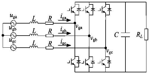
[0085] The main circuit topology of the three-phase voltage-type PWM converter used in the present invention is as follows: figure 1 As shown in the figure, u ga , u gb , u gc are the three-phase voltages on the AC side, i ga i gb i gc are the three-phase currents on the AC side, v ga , v gb , v gc are the three-phase voltages at the input side of the converter, U dc is the DC bus voltage, L and R are the incoming inductance and its equivalent resistance, C is the DC filter capacitor, and the DC side...


PUM


Abstract

The invention discloses a sliding mode power cancellation direct power control method of a three-phase voltage type PWM converter, The actual value of the active pow decreases and the actual value ofthe reactive pow increases and the actual value of the reactive power of the active power decreases, an another non-zero voltage vector is looked for, An improved vector table is obtained, At that same time, according to the sector where the grid voltage position angle is located, Actual value of active power and reactive power and reference value of active power and reactive power, three optimalvoltage vectors are selected from the improved vector table, which can reduce the error between the actual value of active power and reactive power and reference value at the same time, and calculatethe action time of each vector according to the reference value of active power and reactive power. The control algorithm of the method is simple and easy to realize, the approach speed of the arrivalstage can be improved, the output chattering of the system can be suppressed, the steady-state ripple of the active power and the reactive power can be suppressed at the same time, and the current distortion rate is low, so that the system has excellent dynamic and static performance.

Description

technical field [0001] The invention relates to the control field of power electronic power conversion devices, in particular to a sliding mode power offset direct power control method of a three-phase voltage type PWM converter. Background technique [0002] With the continuous development of power electronics technology and control technology, the performance of power converters has been continuously improved, and has been widely used in rectification, AC speed regulation, active filtering, reactive power compensation and new energy grid-connected power generation and other fields. After rapid development in recent years, more and more control methods have been proposed and applied to the control of PWM power converters. The control methods of power converters mainly include grid voltage oriented control (VOC), virtual flux oriented control (VFOC), sliding mode control (sliding mode control, SMC), model predictive control ( model predictive control, MPC) and direct power ...

Claims


Application Information

Patent Timeline
IPC IPC(8): H02M7/219H02M1/12
CPCH02M1/12H02M7/219
Inventor 王延敏
Owner 嘉兴巨腾信息科技有限公司
Learn More