
Push-pull unlocking mechanism for electronic lock

An electronic lock and lock mechanism technology, applied in architectural locks, building structures, non-mechanical transmission-operated locks, etc., can solve the problems of unable to grip the lock handle, difficult to hold, unable to wrap the hand, etc. Simple structure, convenient processing and high reliability

Pending Publication Date: 2019-01-22
广东摩力智能科技有限公司
View PDF0 Cites 0 Cited by
  • Summary
  • Abstract
  • Description
  • Claims
  • Application Information

AI Technical Summary

Problems solved by technology

However, if the handle is wider, such as reaching the width of a credit card, it is not easy to hold, especially for people with smaller hands, the hand cannot wrap around the handle, and the lock handle cannot be grasped tightly. according to

Method used


Image

  • Push-pull unlocking mechanism for electronic lock
  • Push-pull unlocking mechanism for electronic lock
  • Push-pull unlocking mechanism for electronic lock

Examples


Embodiment Construction

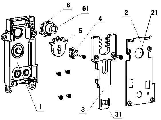
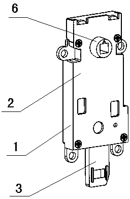
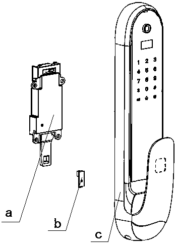
[0016] A preferred embodiment of the present invention, such as Figures 1 to 3 As shown, a push-pull unlocking mechanism a of an electronic lock, the mechanism a is used to be vertically fixed in the front panel c of the electronic lock, the whole of the mechanism a is a rectangular box, including a bottom box 1, a cover The cover plate 2 and the main body on the bottom box 1 are located in the box body and the tail end exposes the box body downwards and the tail end has a square hole 31 and its top is a U-shaped slingshot link piece 3; 4 and lower tooth 5 components, the upper tooth 4 is provided with side teeth and the lower tooth 5 is provided with upper teeth; in the middle there is a sleeve 6 with a square hole 61 for placing the unlocking square bar; The main body of the sleeve 6 is located in the box body and one end thereof protrudes from the corresponding opening 21 on the cover plate 2, the transmission tooth assembly is located in the box body; the inner side of th...


PUM


Abstract

The invention discloses a push-pull unlocking mechanism for an electronic lock. The push-pull unlocking mechanism is vertically and fixedly arranged in a panel of the electronic lock and integrally comprises a bottom box, a cover plate, a slingshot-type connecting rod piece with a U-shaped upper portion, a transmission tooth component and a sleeve, the cover plate covers the bottom box, a body ofthe slingshot-type connecting rod piece is positioned in a box body, the tail end of the slingshot-type connecting rod piece is exposed downwards to the box body and provided with a square hole, an upper layer of the transmission tooth component is provided with side edge teeth, a lower layer of the transmission tooth component is provided with upper side teeth, a square hole for placing an unlocking square rod is formed in the middle of the sleeve, the sleeve and the transmission tooth component are arranged in the box body, teeth are arranged on the inner side edge of a U-shaped opening of the connecting rod piece, lower side teeth are arranged on an outer ring of the sleeve, the teeth of the U-shaped opening of the connecting rod piece are engaged with the side edge teeth on the upper layer of the transmission tooth component, and the upper side teeth on the lower layer of the transmission tooth component are engaged with the lower side teeth of the sleeve. The mechanism is simple in structure, convenient to machine, high in reliability and particularly applicable to advanced electronic locks with high additional values, parts are fewer, and force of a push-pull lock handle is transformed.

Description

technical field [0001] The invention relates to an unlocking mechanism of an electronic lock. Background technique [0002] Currently commonly used electronic locks, including card locks, combination locks, fingerprint locks, etc., the door opening mechanism is generally the same inside and outside, and they all adopt a push-down type. By pressing down on the handle of the lock, the square rod in the central axis of the handle is driven to rotate. , so as to drive the unlocking mechanism of the lock body to rotate, and finally drive the dead bolt to recover into the lock body, so that the door can be opened. In order to hold such a lock handle, it is generally long and narrow in width, so as to be suitable for holding of various sizes of hands. However, if the handle is wider, such as reaching the width of a credit card, it is not easy to hold, especially for people with smaller hands, the hand cannot wrap around the handle, and the lock handle cannot be held tightly. acco...

Claims


Application Information

Patent Timeline
IPC IPC(8): E05B47/00E05B15/00
CPCE05B47/0001E05B15/0013
Inventor 何隆斌
Owner 广东摩力智能科技有限公司
Learn More