
Clean sealed boiler flue gas desulfurization and denitration device with filtering function

A technology for boiler flue gas, desulfurization and denitrification, which is used in cleaning hollow objects, dispersing particle filtration, cleaning methods and appliances, etc., can solve the problem that the inner wall of the cooling tower is easily corroded by chemical substances, does not have the function of cleaning the inner wall of the cooling tower, impurities And the problem of poor dust cleaning efficiency, to achieve the effect of easy dredging and cleaning, increase the service life, and easy to clean

Inactive Publication Date: 2019-01-22
余汉锡
View PDF0 Cites 5 Cited by
  • Summary
  • Abstract
  • Description
  • Claims
  • Application Information

AI Technical Summary

Problems solved by technology

[0004] The purpose of the present invention is to provide a clean and sealed boiler flue gas desulfurization and denitrification device with filtering function, so as to solve the problem that the modern boiler flue gas desulfurization and denitrification device proposed in the above background technology needs to filter the flue gas before the flue gas enters the cooling tower. However, the currently used boiler flue gas desulfurization and denitration efficiency is not good for cleaning impurities and dust in the flue gas, and it does not have the function of cleaning the inner wall of the cooling tower, which makes the cooling tower a long time After use, the inner wall of the cooling tower is easily corroded by chemicals, which makes the service life of the cooling tower poor

Method used


Image

  • Clean sealed boiler flue gas desulfurization and denitration device with filtering function
  • Clean sealed boiler flue gas desulfurization and denitration device with filtering function
  • Clean sealed boiler flue gas desulfurization and denitration device with filtering function

Examples


Embodiment Construction

[0029] The following will clearly and completely describe the technical solutions in the embodiments of the present invention in conjunction with the accompanying drawings in the embodiments of the present invention. Obviously, the described embodiments are only some of the embodiments of the present invention, but not all of them. Based on the embodiments of the present invention, all other embodiments obtained by persons of ordinary skill in the art without making creative efforts belong to the protection scope of the present invention.

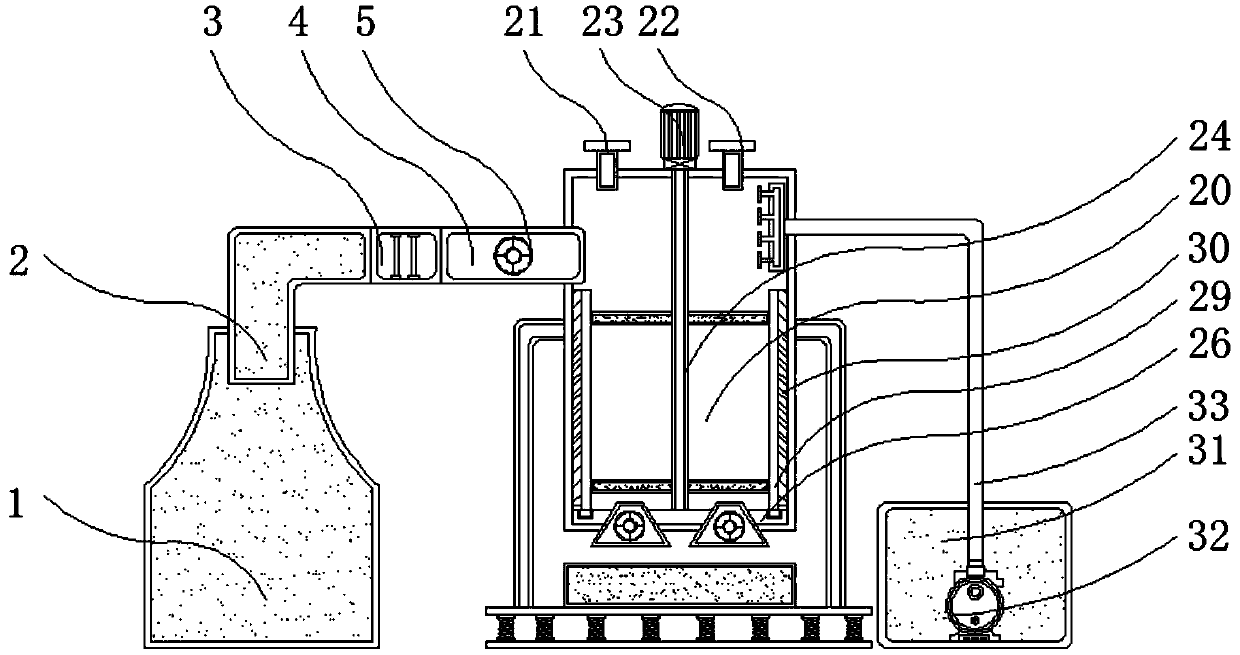
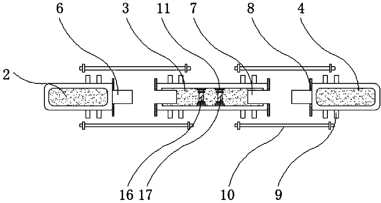
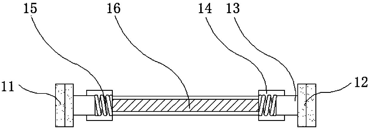
[0030] see Figure 1-7, the present invention provides a technical solution: a clean and sealed boiler flue gas desulfurization and denitrification device with filtering function, including a boiler body 1, a smoke outlet pipe 2, a connecting pipe 3, a smoke inlet pipe 4, a valve 5, and a lock block 6 , lock groove 7, gasket 8, placement bar 9, threaded rod 10, first fixed block 11, second fixed block 12, connecting rod 13, connecting sleev...


PUM


Abstract

The invention discloses a clean sealed boiler flue gas desulfurization and denitration device with a filtering function. The device comprises a boiler body, a placement strip, a cooling tower, a fixing ring, and a water pump, the upper end of the boiler body is seamlessly connected with a smoke-outlet pipe, the outer wall of the cooling tower is seamlessly connected to the input end of a smoke-inlet pipe, the output end of a driving motor is flanged to a rotating shaft, the fixing ring is fixedly welded to the inner bottom end of the cooling tower, and the output end of a condensing tube is injection-connected to a collecting pipe. The clean sealed boiler flue gas desulfurization and denitration device with filtering function has a connection manner of slot connection between the smoke-outlet pipe and the connecting pipe and between the connecting pipe and the smoke-inlet pipe, a user can conveniently perform disassembly and assembly between the smoke-outlet pipe and the connecting pipe and between the connecting pipe and the smoke-inlet pipe, the situation that the pipe connection is too long and the inside is prone to blockage is avoided, so that the user can timely dredge and clean the inside of the pipe, and a sealing gasket is beneficial to increase of the sealing performance between the pipes.

Description

technical field [0001] The invention relates to the related technical field of boiler flue gas treatment, in particular to a clean and sealed boiler flue gas desulfurization and denitrification device with filtering function. Background technique [0002] The dust contained in the boiler flue gas, including fly ash, carbon black, sulfur and nitrogen oxides, is a substance that pollutes the atmosphere. If it is not purified, its emission index can reach several times to dozens of times the environmental protection regulation index. Measures to discharge these substances include pre-combustion treatment, improved combustion technology, dust removal, desulfurization and denitrification, etc. The use of high chimneys can only reduce the concentration of pollutants in the atmosphere near the chimney. Therefore, in order to avoid the impact on the air in the natural environment, it is necessary to The flue gas in the boiler is desulfurized and denitrified, so the boiler flue gas d...

Claims


Application Information

Patent Timeline
IPC IPC(8): B01D53/75B01D53/76B01D53/60B01D46/12B08B9/36
CPCB01D53/75B01D46/12B01D53/04B01D53/60B01D53/76B08B9/36
Inventor 余汉锡
Owner 余汉锡
Learn More