
A degassing assembly line for electric cables

An air flow and cable technology, applied in the field of degassing water lines for cables, can solve the problems of moving to the inner layer of insulation, unsatisfactory effect, reverse movement of space charges, etc., saving degassing time, good degassing effect, and improving production. The effect of efficiency

Active Publication Date: 2019-01-18
HENGTONG SUBMARINE POWER CABLE CO LTD +1
View PDF5 Cites 1 Cited by
  • Summary
  • Abstract
  • Description
  • Claims
  • Application Information

AI Technical Summary

Problems solved by technology

Domestic submarine cable manufacturers have obtained the performance of high-voltage 220kV AC submarine cable 30km without factory joints, and 500kV AC submarine cable 18km without factory joint performance. At present, the domestic large-length 500kV DC submarine cable is also in the research and development process, so the manufacture of large-length submarine cables is a submarine cable. The trend of development, while the traditional submarine cable degassing room uses heating air around the degassing room, but the effect is not ideal in the degassing process of long-length submarine cables
Especially for the degassing of DC cables, due to the current design of the degassing room, the heat conduction of the insulated core is conducted from the outer layer of the insulated core to the inner layer of the insulated core, and the temperature gradient will cause the space charge to move to the inner layer of the insulation. In the actual operation of the DC cable, due to the heating of the cable conductor, the heat conduction of the insulated core is conducted from the inner layer of the insulated core to the outer layer of the insulated core, resulting in the risk of reverse movement of space charges, so there is a potential for DC cables security risk

Method used


Image

  • A degassing assembly line for electric cables
  • A degassing assembly line for electric cables
  • A degassing assembly line for electric cables

Examples


Embodiment Construction

[0022] The preferred embodiments of the present invention will be described in detail below in conjunction with the accompanying drawings, so that the advantages and features of the present invention can be more easily understood by those skilled in the art, so as to define the protection scope of the present invention more clearly.

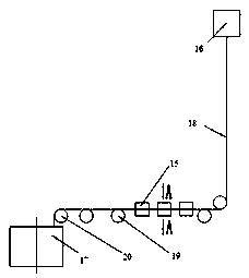
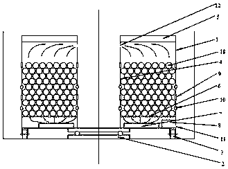
[0023] see Figure 1 to Figure 3 , the embodiment of the present invention includes: a degassing water line for cables, including: a vertical tower extruder 16 and a degassing room 17, the vertical tower extruder 16 and the degassing room 17 are insulated by cables The wire cores 18 are connected, and the tower extruder 16 is used to produce the cable insulation wire cores 18 .

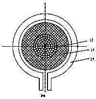
[0024] The cable insulation core 18 is composed of a copper core stranded conductor 13 and a shielding insulation layer 14 , and the shielding insulation layer 14 is wrapped on the outer wall of the copper core stranded conductor 13 .

[0025] Between the vertical tower...


PUM


Abstract

The invention discloses a degassing assembly line for electric cable, comprising a vertical tower extruder and a degassing chamber, wherein, the vertical tower extruder and the degassing chamber are connected with each other through a cable insulation wire core; The cable insulation wire core is composed of a copper core stranded conductor and a shielding insulation layer, and the shielding insulation layer is wrapped on the outer wall of the copper core stranded conductor. A plurality of supporting rollers and the steering supporting rollers are arranged between the vertical tower extruder and the degassing chamber; A plurality of high-frequency heating coils are arranged between the two supporting rollers, the high-frequency heating coils are circular rings with openings at the bottom end, and the cable insulation wire core passes through the high-frequency heating coils. As that high-frequency heat coil heats the cable conductor in the production process of the insulated wire core,the degassing assembly line realizes the heating while producing the insulated wire core, achieves the on-line degassing effect, saves the degassing time, improves the production efficiency of the cable, and has better degassing effect.

Description

technical field [0001] The invention belongs to the field of power cables, and in particular relates to a degassing line for cables. Background technique [0002] With the rapid development of island development strategies and offshore renewable energy power generation, offshore wind power is expanding rapidly, and the demand for submarine high-voltage power cables is increasing. Domestic submarine cable manufacturers have obtained the performance of high-voltage 220kV AC submarine cable 30km without factory joints, and 500kV AC submarine cable 18km without factory joint performance. At present, the domestic large-length 500kV DC submarine cable is also in the research and development process, so the manufacture of large-length submarine cables is a submarine cable. The trend of development, while the traditional submarine cable degassing room uses heating air around the degassing room, but the effect is not ideal in the degassing process of long-length submarine cables. Es...

Claims


Application Information

Patent Timeline
Patent Type & Authority Applications(China)
IPC IPC(8): H01B13/00
CPCH01B13/0016
Inventor 梅文杰米建忠狄健潘文林钱志康
Owner HENGTONG SUBMARINE POWER CABLE CO LTD
Learn More