
Loader working hydraulic system

A technology of hydraulic system and loader, which is applied in the field of hydraulic system of loader work, and can solve the problems that affect the lifting and shoveling of the whole machine, etc.

Active Publication Date: 2020-11-17
GUANGXI LIUGONG MASCH CO LTD
View PDF6 Cites 0 Cited by
  • Summary
  • Abstract
  • Description
  • Claims
  • Application Information

AI Technical Summary

Problems solved by technology

[0003] The invention provides a working hydraulic system of a loader. The system can solve the problem that the adjustment of the working pressure of the attachment oil cylinder will affect the lifting and shoveling of the whole machine and the working pressure of the attachment when the attachment is operating under different working conditions. tuning problem

Method used


Image

  • Loader working hydraulic system
  • Loader working hydraulic system

Examples


Embodiment 1

[0018] The present invention will be described in further detail below in conjunction with accompanying drawing embodiment:

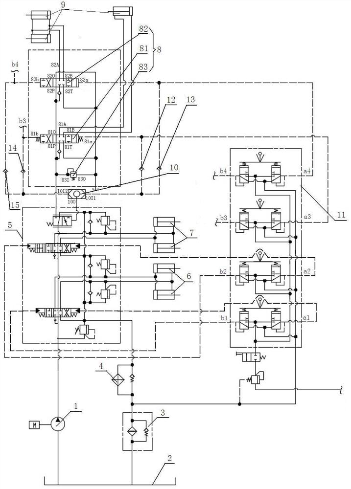
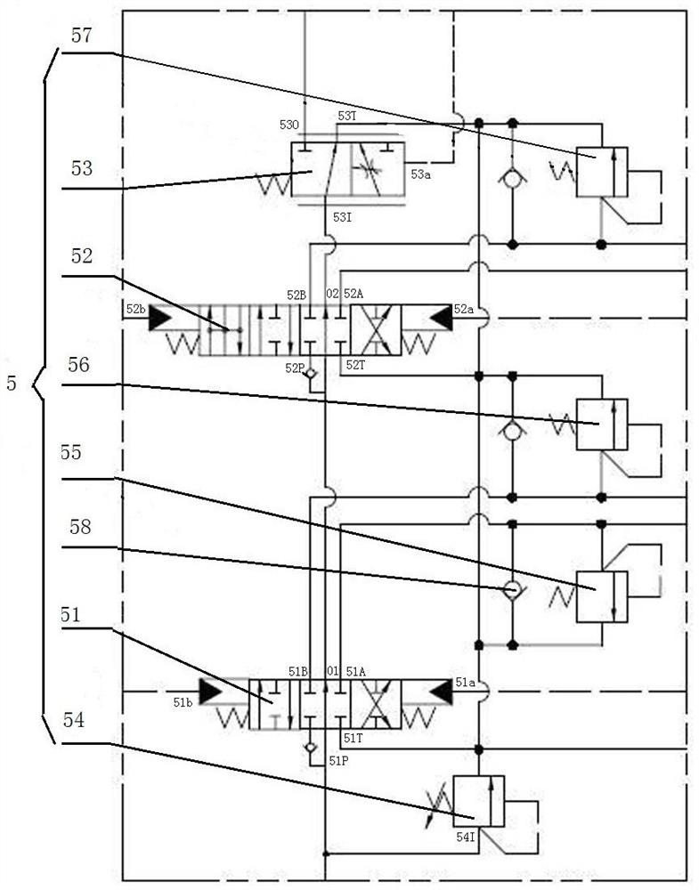
[0019] figure 1 , figure 2The working hydraulic system of the loader shown includes the bucket cylinder 6, the boom cylinder 7 and the attachment cylinder 9 that provide pressure oil through the oil pump 1, and the oil circuit between the bucket cylinder 6, the boom cylinder 7 and the oil pump 1 is set There is a distribution valve 5 for the boom rotary bucket joint; an attachment distribution valve 8 is provided on the oil circuit between the boom rotary bucket joint distribution valve 5 and the attachment cylinder 9; the boom rotary bucket joint distribution valve 5 includes the rotary bucket control valve Core 51, boom control spool 52, priority valve 53, first safety valve 54, first bucket overflow valve 55, second bucket overflow valve 56 and boom overflow valve 57; bucket control spool 51. The boom control spool 52 and the priority valve 53 are...

Embodiment 2

[0024] There are four attachment control spools connected in series; the rest are the same as in the first embodiment.


PUM


Abstract

The invention discloses a loading-machine working hydraulic system, and belongs to the technical field of engineering machines. The loading-machine working hydraulic system comprises a movable-arm rotating-bucket cascading distribution valve arranged between movable-arm oil cylinders and an oil pump and an accessory cascading distribution valve arranged between the movable-arm rotating-bucket cascading distribution valve and accessory oil cylinders; the movable-arm rotating-bucket cascading distribution valve comprises a rotating-bucket control valve core, a movable-arm control valve core anda preferential valve, wherein the rotating-bucket control valve core, the movable-arm control valve core and the preferential core are sequentially connected between the oil cylinder and the accessorycascading distribution valve; a first safety valve is arranged between an oil inlet of the rotating-bucket control valve core and an oil returning opening of the rotating-bucket control valve core; the accessory cascading distribution valve comprises at least two accessory control valve cores, and a second safety valve is arranged between an oil inlet and an oil returning opening of the accessorycontrol valve core connected with the preferential valve; the hydraulic control end of the preferential valve is correspondingly connected with the hydraulic control ends of all the accessory controlvalve cores through shuttle valves. By means of the loading-machine working hydraulic system, the problems that the lifting work capacity, the shoveling work capacity and the like of a whole machinecan be influenced when the working pressure of the accessory oil cylinders is adjusted, and the accessory cascading working pressure is nonadjustable when accessories work under different working conditions are solved.

Description

technical field [0001] The invention relates to the technical field of engineering machinery, in particular to a working hydraulic system of a loader. Background technique [0002] The working hydraulic system of the loader is a device that uses oil as the working medium, uses the pressure energy of the oil and controls the working devices such as the boom, bucket and attachment of the loader through control valves and other accessories. The existing working hydraulic system of the loader has the following problems because the working pressures of the boom linkage, the bucket linkage and the attachment linkage are set to be controlled by the same pressure regulating device: 1. The pressure is small. When the working pressure of the attachment cylinder is adjusted, the working pressure of the boom cylinder and bucket cylinder will change accordingly, which will affect the lifting and shoveling of the whole machine; 2. Due to the attachment When working in different working c...

Claims


Application Information

Patent Timeline
Patent Type & Authority Patents(China)
IPC IPC(8): E02F9/22F15B11/16F15B13/06F15B21/00F15B21/04
CPCE02F9/2221E02F9/226E02F9/2267F15B11/16F15B13/06F15B21/001F15B21/041F15B21/042
Inventor 韦茂志梁振国周进平赵丽丽石军锋孙立州
Owner GUANGXI LIUGONG MASCH CO LTD
Learn More