


Quick Research
Generate reliable direction feasibility study reports for your R&D in just a few steps.

Technical Q&A
Discover and master advanced knowledge NOW. Basics, ideas, possibilities, all at once.

Find Solutions
As an expert in R&D theories, this can generate solutions to your technical problems instantly.

Evaluate Feasibility
Analyze your overall solution with one click, know your potential R&D risks in advance.

Monitor Landscape
Get weekly tech updates, stay abreast of the latest tech innovations and key insights.
Dirt cleaning device for hole mold of mold
A cleaning device and a technology for mold holes, which are applied in the direction of cleaning methods using tools, cleaning methods and utensils, and cleaning methods using liquids, etc., can solve problems such as difficult to clean in all directions and cannot adapt to different sizes, and improve cleaning efficiency. , saving cleaning time and improving the convenience of operation
- Summary
- Abstract
- Description
- Claims
- Application Information
AI Technical Summary
Problems solved by technology
Method used
Image

Examples
Embodiment 1
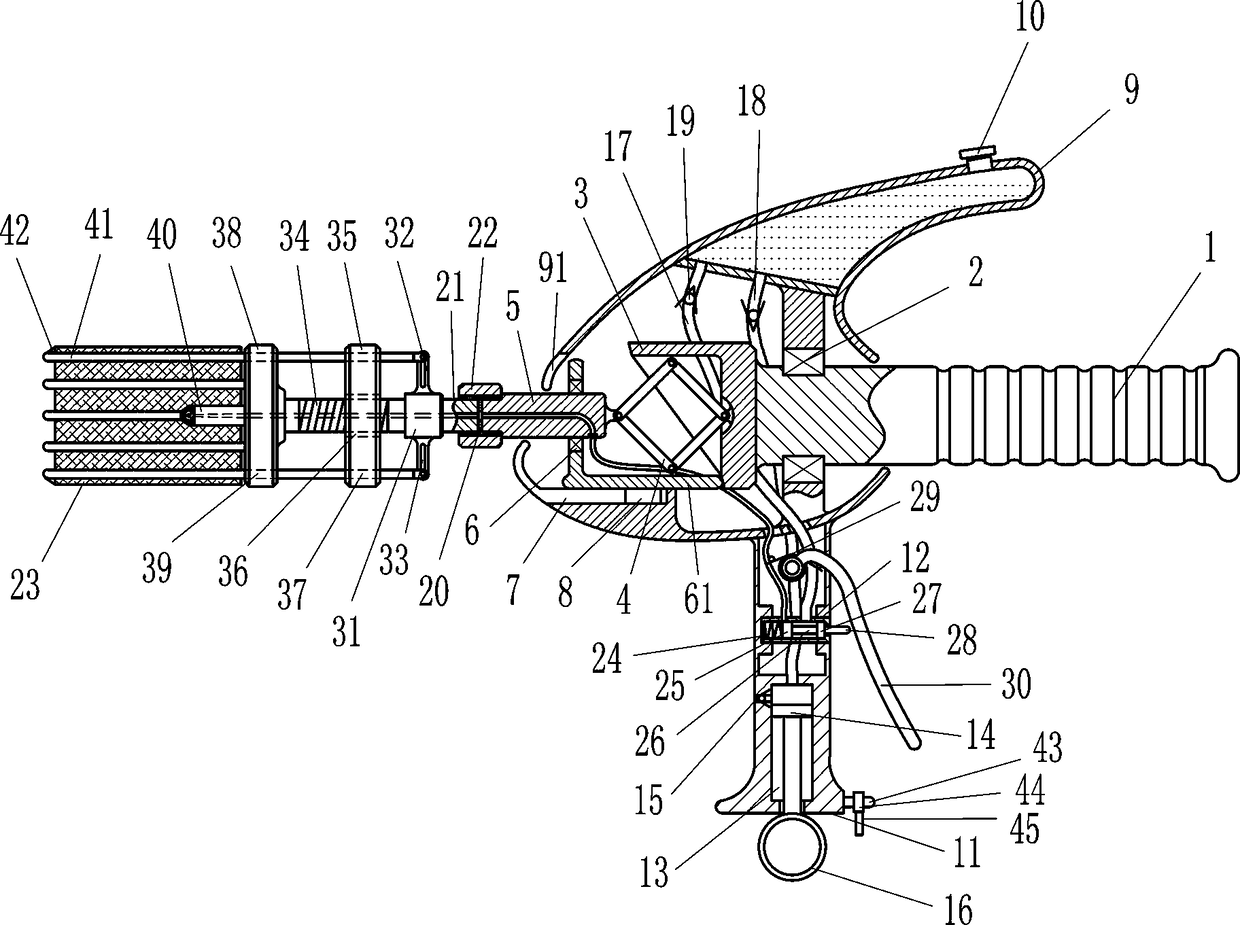
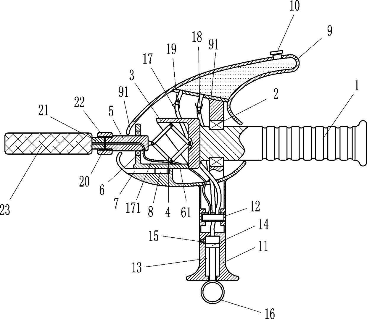
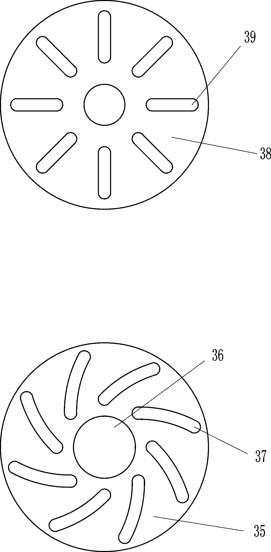
[0019] A mold hole mold scale cleaning device, such as Figure 1-3 As shown, it includes a handle 1, a first bearing seat 2, a slotted pipe with an inclined plane 3, a telescopic frame 4, a cylinder 5, a second bearing seat 6, a slider 8, a casing 9, a partition plate 91, and a cover 10 , handle 11, cylinder 12, piston 14, air inlet 15, pull rod 16, input pipe 17, thin hose 171, air inlet pipe 18, one-way valve 19, rubber pad 20, threaded mounting rod 21, first nut 22 and cotton sleeve 23, the first bearing seat 2 is installed on the left part of the handle 1, the left end of the handle 1 is connected with a slotted pipe 3 with an inclined plane, the inner right wall of the slotted pipe 3 with an inclined plane is connected with a telescopic frame 4, and the first bearing seat 2 The outer side is connected with a casing 9, the slotted pipe 3 is located in the casing 9, the upper part between the left and right walls of the casing 9 is connected with a partition plate 91, the t...
Embodiment 2
[0021] A mold hole mold scale cleaning device, such as Figure 1-3As shown, it includes a handle 1, a first bearing seat 2, a slotted pipe with an inclined plane 3, a telescopic frame 4, a cylinder 5, a second bearing seat 6, a slider 8, a casing 9, a partition plate 91, and a cover 10 , handle 11, cylinder 12, piston 14, air inlet 15, pull rod 16, input pipe 17, thin hose 171, air inlet pipe 18, one-way valve 19, rubber pad 20, threaded mounting rod 21, first nut 22 and cotton sleeve 23, the first bearing seat 2 is installed on the left part of the handle 1, the left end of the handle 1 is connected with a slotted tube 3 with an inclined plane, the inner right wall of the slotted tube 3 with an inclined plane is connected with a telescopic frame 4, and the first bearing seat 2 The outer side is connected with a casing 9, the grooved pipe 3 is located in the casing 9, the upper part between the left and right walls of the casing 9 is connected with a partition plate 91, the to...
Embodiment 3
[0024] A device for cleaning mold hole mold scale, such as Figure 1-3 As shown, it includes a handle 1, a first bearing seat 2, a slotted pipe with an inclined plane 3, a telescopic frame 4, a cylinder 5, a second bearing seat 6, a slider 8, a casing 9, a partition plate 91, and a cover 10 , handle 11, cylinder 12, piston 14, air inlet 15, pull rod 16, input pipe 17, thin hose 171, air inlet pipe 18, one-way valve 19, rubber pad 20, threaded mounting rod 21, first nut 22 and cotton sleeve 23, the first bearing seat 2 is installed on the left part of the handle 1, the left end of the handle 1 is connected with a slotted tube 3 with an inclined plane, the inner right wall of the slotted tube 3 with an inclined plane is connected with a telescopic frame 4, and the first bearing seat 2 The outer side is connected with a casing 9, the grooved pipe 3 is located in the casing 9, the upper part between the left and right walls of the casing 9 is connected with a partition plate 91, t...
PUM
 Abstract
Description
Claims
Application Information
 - R&D Engineer
- R&D Manager
- IP Professional
- Industry Leading Data Capabilities
- Powerful AI technology
- Patent DNA Extraction
Browse by: Latest US Patents, China's latest patents, Technical Efficacy Thesaurus, Application Domain, Technology Topic, Popular Technical Reports.
© 2024 PatSnap. All rights reserved.Legal|Privacy policy|Modern Slavery Act Transparency Statement|Sitemap|About US| Contact US: help@patsnap.com