
Grinding machine

A grinding machine and grinding disc technology, which is applied in the direction of grinding machines, machine tools suitable for grinding workpiece planes, grinding/polishing equipment, etc., can solve problems such as ineffective heat dissipation, easy heating of control components, and burnt internal components. Simple and practical, improve the heat dissipation effect, and adjust the effect of large angle

Inactive Publication Date: 2019-01-18
ZHEJIANG BURLEY TOOLS
View PDF0 Cites 3 Cited by
  • Summary
  • Abstract
  • Description
  • Claims
  • Application Information

AI Technical Summary

Problems solved by technology

During the grinding process, the grinding disc will be fine-tuned in all directions according to the flatness of the wall. In the prior art, the grinding wheel is fixed on the grinding disc, and the grinding wheel can be fine-tuned relative to the grinding disc. This structure is due to the structure of the part itself. The fine-tuning angle is small, and there are certain limitations in use; secondly, the grinding machine generally includes a grinding disc, which is provided with a grinding wheel for grinding, and dust suction holes are set on the grinding wheel and the grinding disc. There are different specifications for the aperture of the hole. In order to adapt to different grinding wheels, different grinding discs need to be configured, thereby increasing the corresponding use cost; Some products have large defects in the design of the heat dissipation mechanism, which makes the heat dissipation effect not obvious and easily causes internal components to burn out

Method used


Image

  • Grinding machine
  • Grinding machine
  • Grinding machine

Examples


Embodiment Construction

[0020] The following will clearly and completely describe the technical solutions in the embodiments of the present invention with reference to the accompanying drawings in the embodiments of the present invention. Obviously, the described embodiments are only some, not all, embodiments of the present invention. Based on the embodiments of the present invention, all other embodiments obtained by persons of ordinary skill in the art without creative efforts fall within the protection scope of the present invention.

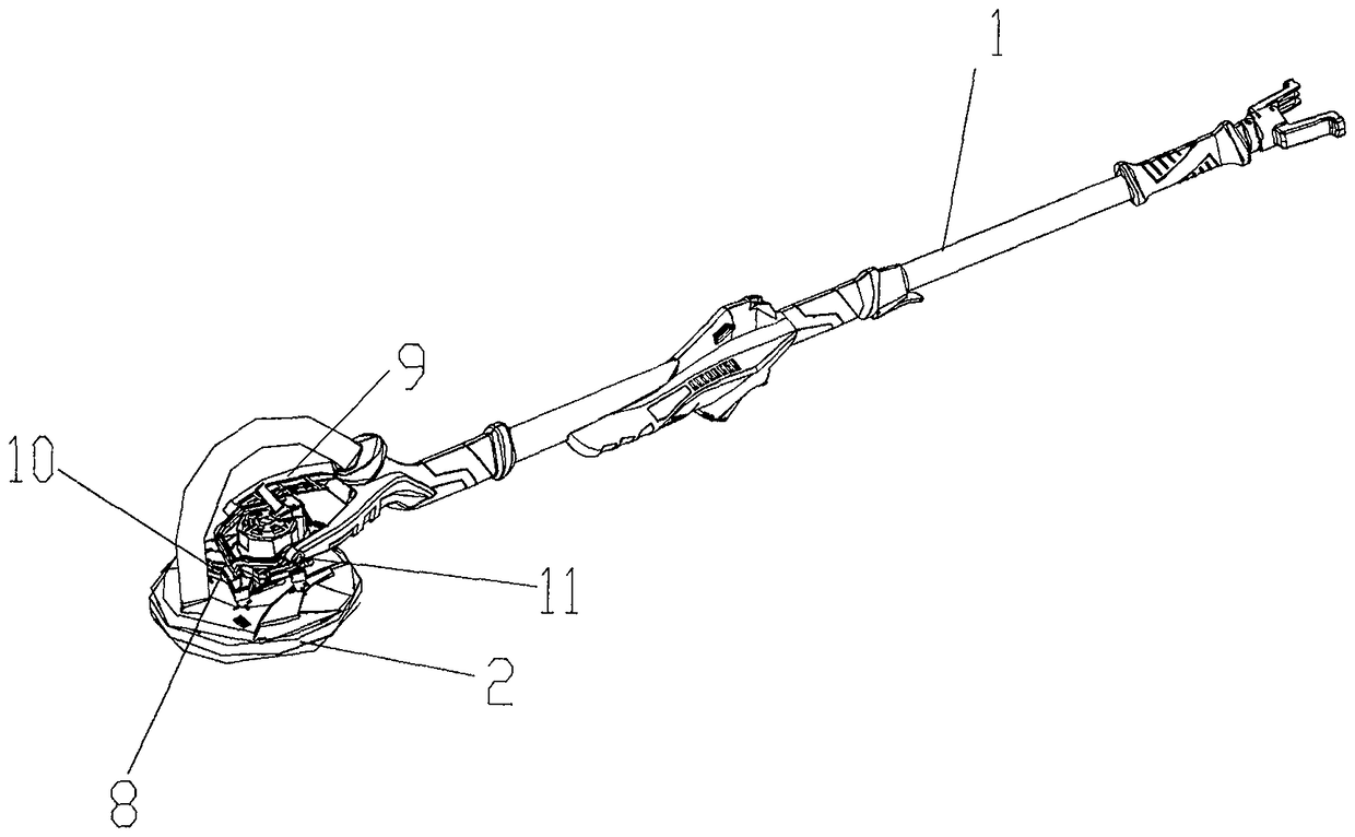
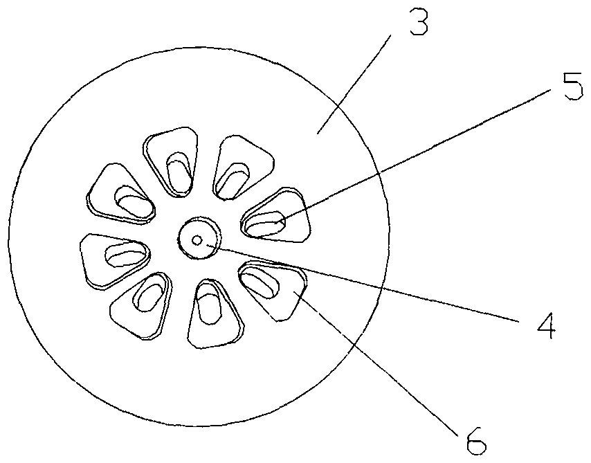
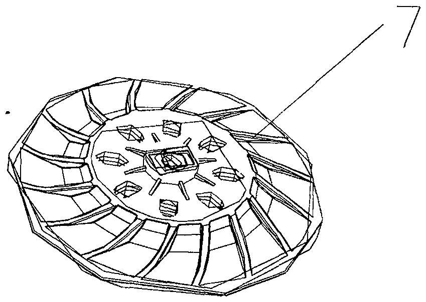
[0021] Such as Figure 1-4 Shown, a kind of grinding machine comprises machine head assembly and handle 1, and described machine head assembly is connected with handle 1, and described machine head assembly includes grinding disc 2, driving motor and control system, and described grinding disc is connected with driving motor, and The driving motor is connected with the control system, and also includes the universal control mechanism and heat dissipation structure ...


PUM


Abstract

The invention provides a grinding machine, comprising a handpiece assembly and a handle. The handpiece assembly is connected to the handle. The handpiece assembly comprises a grinding disk, a drive motor and a control system. The grinding disk is connected to the drive motor. The drive motor is connected to the control system. The machine further includes a universal control mechanism of a handpiece and a heat dissipation structure. The grinding disk includes a grinding disk body. The center of the grinding disk body is provided with a rotating shaft mounting hole. The grinding disk body is provided with a dust collecting hole. The dust collecting hole comprises an inner hole and an outer hole, wherein the outer hole and the inner hole are connected to each other. The opening area of the outer hole is larger than the opening area of the inner hole. The universal control mechanism is arranged to realize jogging of the handpiece on each direction. Compared with the prior art, the grinding machine has larger adjusting angles, and the structure is simple and practical. The dust collecting hole includes the inner hole and the outer hole, and the outer hole and the inner hole are connected to each other, and the opening area of the outer hole is larger than that of the inner hole, so as to adapt to grinding wheels in different specifications. Heat is transmitted to the handle of thegrinding machine through the heat dissipation structure, and heat dissipation area is increased by the handle, thereby improving the heat dissipation effect.

Description

technical field [0001] The invention belongs to the technical field of grinding machines, in particular to a grinding machine. Background technique [0002] Wall sanders are a well-established technology for sanding and cleaning walls before they are painted, painted or wallpapered. During the grinding process, the grinding disc will be fine-tuned in all directions according to the flatness of the wall. In the prior art, the grinding wheel is fixed on the grinding disc, and the grinding wheel can be fine-tuned relative to the grinding disc. This structure is due to the structure of the part itself. The fine-tuning angle is small, and there are certain limitations in use; secondly, the grinding machine generally includes a grinding disc, which is provided with a grinding wheel for grinding, and dust suction holes are set on the grinding wheel and the grinding disc. There are different specifications for the aperture of the hole. In order to adapt to different grinding wheels...

Claims


Application Information

Patent Timeline
Patent Type & Authority Applications(China)
IPC IPC(8): B24B7/18B24B55/10B24B55/02
CPCB24B7/184B24B7/186B24B55/02B24B55/102
Inventor 李挺进
Owner ZHEJIANG BURLEY TOOLS
Learn More