
Printing and dyeing raw material mixer

A technology for mixers and raw materials, applied in mixers, jitter/oscillation/vibration mixers, mixers with rotating stirring devices, etc., can solve the problem that fixed blocks are installed on the bottom of the movable plate through fastening screws, and the movable block and The fixed blocks are connected by the second connecting rod, and the edge of the movable plate away from the fixed plate is provided with a vertical support frame. The internal installation of the support frame cannot simulate manual stirring, etc., so as to increase the effect of stirring

Inactive Publication Date: 2019-01-18
罗茜
View PDF6 Cites 5 Cited by
  • Summary
  • Abstract
  • Description
  • Claims
  • Application Information

AI Technical Summary

Problems solved by technology

[0002] For example, the publication number CN108355536A is a kind of printing and dyeing raw material mixing machine, which includes a housing. The bottom inner wall of the housing is fixedly connected with a mounting seat by fastening screws. Both sides of the mounting seat are welded with fixing plates, and the bottom of the fixing plate is preset. There are movable blocks placed in the chute, two sets of electric slide rails are installed on the outer wall of the mounting seat, sliders are placed on the electric slide rails, the movable block is connected with the slide block through the first connecting rod, and the fixed plate There is a long and straight through groove inside, and the movable plate is slidingly connected in the through groove. The fixed block is installed on the bottom of the movable plate through fastening screws. The movable block and the fixed block are connected by the second connecting rod, and the movable plate is far away from the fixed One side edge of the plate is provided with a vertical support frame, and a heating pipe is installed inside the support frame; the disadvantage of this invention is that it cannot simulate manual stirring, and cannot control the amount of material supplied according to the demand

Method used


Image

  • Printing and dyeing raw material mixer
  • Printing and dyeing raw material mixer
  • Printing and dyeing raw material mixer

Examples


specific Embodiment approach 1

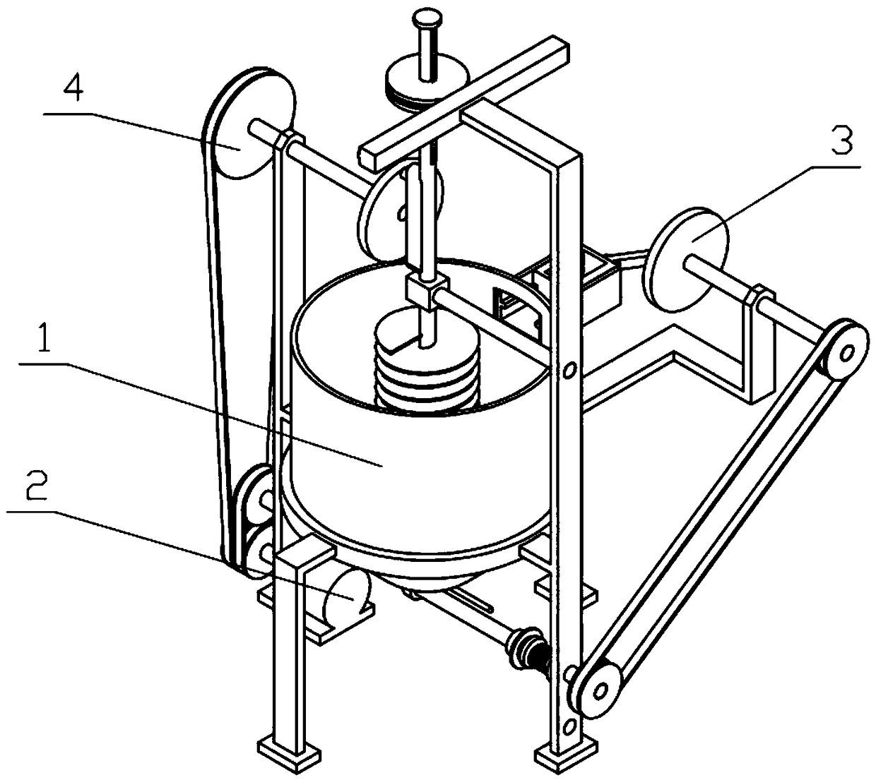
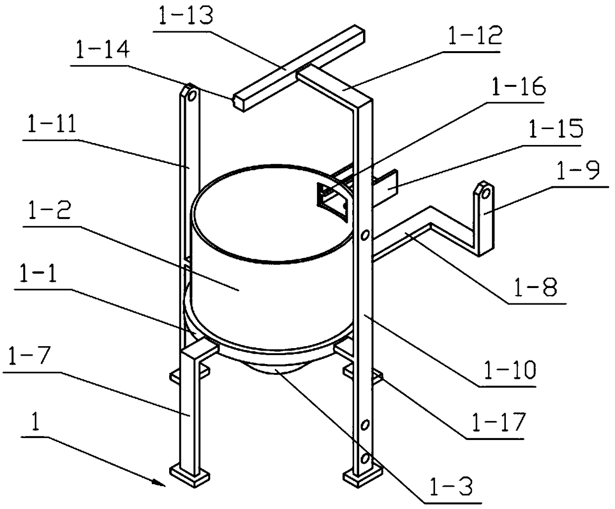
[0029] Combine below Figure 1-10 Describe this embodiment, a printing and dyeing raw material mixer, including the whole machine support 1, power mechanism 2, feeding mechanism 3 and stirring mechanism 4, can drive the feeding mechanism 3 and stirring mechanism 4 to move simultaneously through the power mechanism 2, through The threaded cylinder 2-6 set on the power mechanism 2, the push threaded rod 2-7 and the sliding cylinder 2-8 can realize the timing transmission of the power mechanism 2, and control the time when the power mechanism 2 drives the feeding mechanism 3 to move and control the amount of feed. how much; by the diameter of the stirring pulley 4-2 greater than the diameter of the power pulley 2-2, the effect of speed reduction and twisting is played so that the power on the power mechanism 2 is suitable for the power required by the stirring mechanism 4, and the stirring mechanism 4 is in the following The axis of the stirring shaft III 4-12 arranged on it rota...


PUM


Abstract

The invention relates to a mixer, in particular to a printing and dyeing raw material mixer which comprises a whole machine bracket, a power mechanism, a material supply mechanism and a stirring mechanism; the material supply mechanism and the stirring mechanism can be driven by the power mechanism to move at the same time; timing transmission of the power mechanism can be realized through a threaded cylinder, a push threaded rod and a sliding cylinder arranged on the power mechanism; the material supply quantity is controlled by controlling the time that the power mechanism drives the material supply mechanism to move; the effect of reducing the speed and rising the torque with the diameter of a stirring belt wheel being larger than the diameter of a power belt wheel, so that the power applied to the power mechanism is suitable for the power required for the stirring mechanism; and the stirring mechanism rotates by taking an axis of a stirring shaft III arranged on the stirring mechanism as the center and performs simulation on manual stirring, and a stirring gear enables the stirring mechanism to generate autoroatation while the stirring mechanism generates swing to improve the stirring effect.

Description

technical field [0001] The invention relates to a mixing machine, more specifically a printing and dyeing raw material mixing machine. Background technique [0002] For example, the publication number CN108355536A is a kind of printing and dyeing raw material mixing machine, which includes a housing. The bottom inner wall of the housing is fixedly connected with a mounting seat by fastening screws. Both sides of the mounting seat are welded with fixing plates, and the bottom of the fixing plate is preset. There are movable blocks placed in the chute, two sets of electric slide rails are installed on the outer wall of the mounting seat, sliders are placed on the electric slide rails, the movable block is connected with the slide block through the first connecting rod, and the fixed plate There is a long and straight through groove inside, and the movable plate is slidingly connected in the through groove. The fixed block is installed on the bottom of the movable plate through...

Claims


Application Information

Patent Timeline
IPC IPC(8): B01F11/00B01F7/00
CPCB01F27/1143B01F31/445B01F2101/30
Inventor 罗茜
Owner 罗茜
Learn More