A new energy vehicle equipment
A technology for new energy vehicles and equipment, applied in vehicle components, auxiliary drive devices, control devices, etc., can solve the problems of unavoidable current overload loss or damage of automobile motor coils, inability to realize driving force transmission, and protection of automobile motors, etc. Compact structure, solving overcurrent loss or damage, fast and stable transmission ratio
- Summary
- Abstract
- Description
- Claims
- Application Information
AI Technical Summary
Problems solved by technology
Method used
Image
Examples
specific Embodiment approach 1
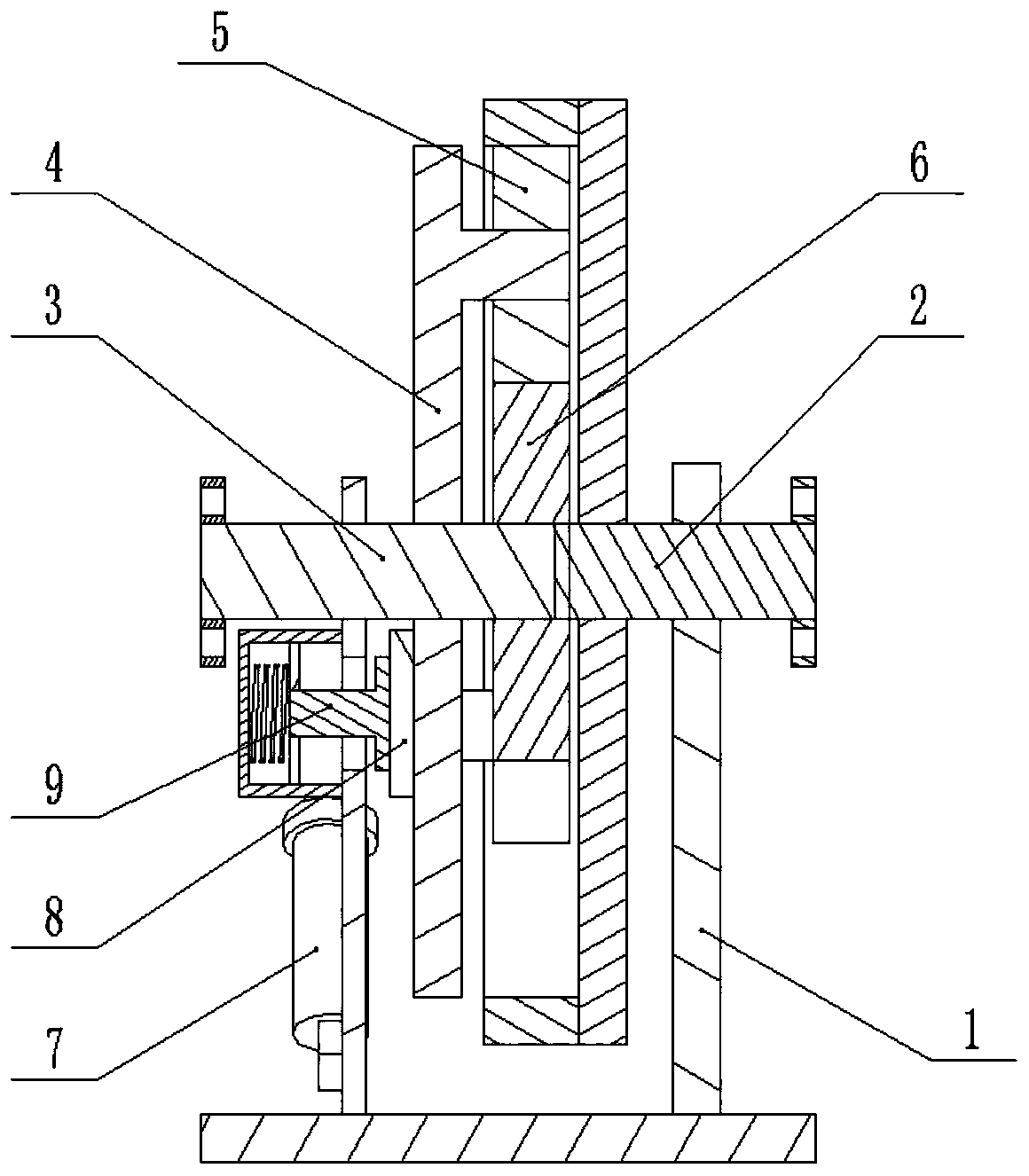
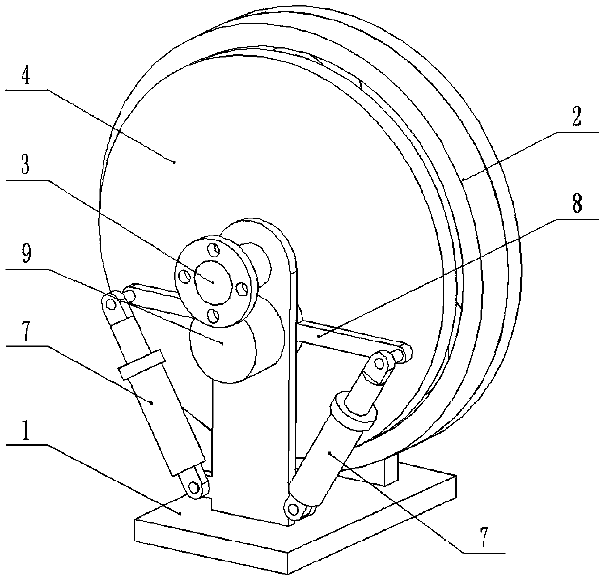
[0028] Combine below Figure 1-9 Describe this embodiment, a new energy vehicle equipment, including drive shaft frame 1, output shaft assembly 2, input shaft 3, intermediate gear frame 4, intermediate gear 5, sun gear 6 and elastic telescopic shaft 7, the output shaft assembly 2 rotatably connected to one end of the drive shaft frame 1, the input shaft 3 is rotatably connected to the other end of the drive shaft frame 1, the intermediate gear frame 4 is rotatably connected to the input shaft 3, and one end of the elastic telescopic shaft 7 is hinged Connected to the eccentric position of the intermediate gear frame 4, the other end of the elastic telescopic shaft 7 is hingedly connected to the drive shaft frame 1, the sun gear 6 is fixedly connected to the input shaft 3, and the intermediate gear 5 is rotatably connected to the intermediate gear frame 4, the intermediate gear 5 meshes with the sun gear 6, and the intermediate gear 5 and the output shaft assembly 2 are connect...
specific Embodiment approach 2
[0030] Combine below Figure 1-9Describe this embodiment, this embodiment will further explain the first embodiment, the friction disc assembly 8 is fixedly connected to the intermediate gear frame 4, the elastic pressing assembly 9 is fixedly connected to the drive shaft frame 1, and the friction disc The component 8 is in frictional contact with the elastic compression component 9; through the elastic compression component 9, the friction disc component 8 is elastically compressed, and when the friction disc component 8 rotates around the input shaft 3 with the intermediate gear frame 4 in a small range, the friction disc component 8 and the elastic compression component The frictional contact of the tight component 9 produces frictional damping, and the friction between the friction disc component 8 and the elastic compression component 9 consumes part of the kinetic energy of the intermediate gear frame 4 when it rotates in a small range, and then quickly realizes the rapid...
specific Embodiment approach 3
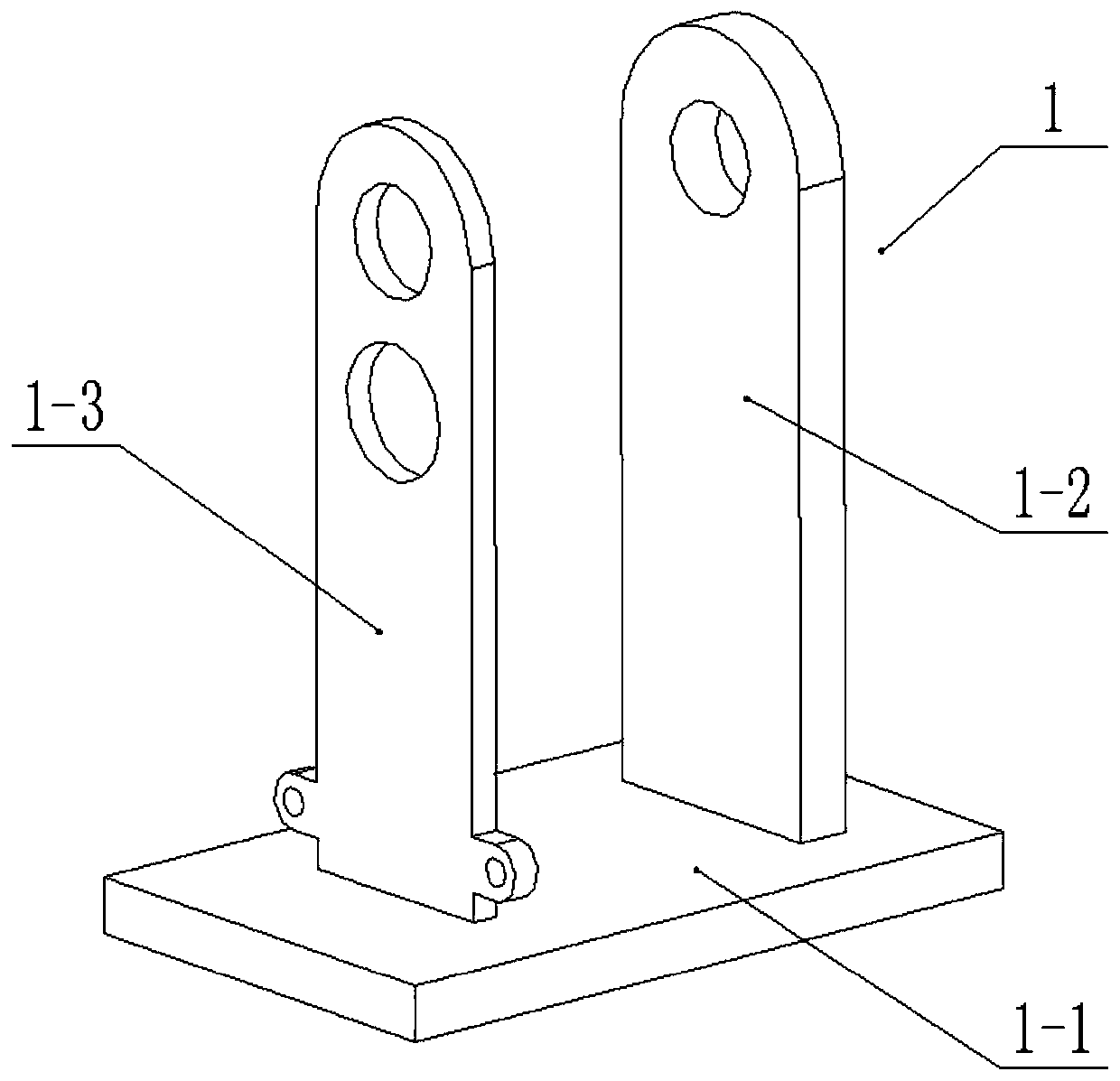
[0032] Combine below Figure 1-9 This embodiment will be described. This embodiment will further describe Embodiment 1. The drive shaft frame 1 includes a base 1-1, an output shaft frame 1-2, and an input shaft frame 1-3. The output shaft frame 1-2 and The input shaft frame 1-3 is fixedly connected to the base 1-1, the output shaft assembly 2 is rotatably connected to the output shaft frame 1-2, and the input shaft 3 is rotatably connected to the input shaft frame 1-3. The output shaft assembly 2 is coaxial with the input shaft 3 .
PUM
 Abstract
Description
Claims
Application Information
 - R&D Engineer
- R&D Manager
- IP Professional
- Industry Leading Data Capabilities
- Powerful AI technology
- Patent DNA Extraction
Browse by: Latest US Patents, China's latest patents, Technical Efficacy Thesaurus, Application Domain, Technology Topic, Popular Technical Reports.
© 2024 PatSnap. All rights reserved.Legal|Privacy policy|Modern Slavery Act Transparency Statement|Sitemap|About US| Contact US: help@patsnap.com


