
Transformer moisture breather quick change flange

A technology of moisture absorbers and transformers, applied in the direction of transformer/inductor cooling, etc., can solve the problems of inconvenient disassembly of moisture absorbers, and achieve the effects of convenient replacement of moisture absorbers, convenient installation, and simple principle

Active Publication Date: 2022-04-19
STATE GRID TIANJIN ELECTRIC POWER +1
View PDF2 Cites 0 Cited by
  • Summary
  • Abstract
  • Description
  • Claims
  • Application Information

AI Technical Summary

Problems solved by technology

[0004] The purpose of the present invention is to overcome the deficiencies of the prior art, to provide a fast replacement flange that is easy to install and can ensure the normal operation of the dehydrator, can facilitate the detachment of the dehydrator, and avoid the inconvenient detachment of the dehydrator due to corrosion of the screws. It is convenient for operation and maintenance personnel to replace the dehumidifier, to ensure the safety of operators, and to prevent accidents that damage the dehydrator and the flange of the dehydrator.

Method used


Image

  • Transformer moisture breather quick change flange
  • Transformer moisture breather quick change flange
  • Transformer moisture breather quick change flange

Examples


Embodiment Construction

[0017] The present invention will be further described in detail below in conjunction with the accompanying drawings and through specific embodiments. The following embodiments are only descriptive, not restrictive, and cannot limit the protection scope of the present invention.

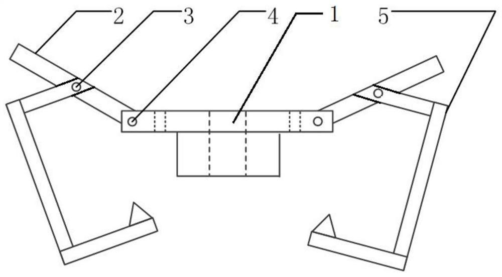
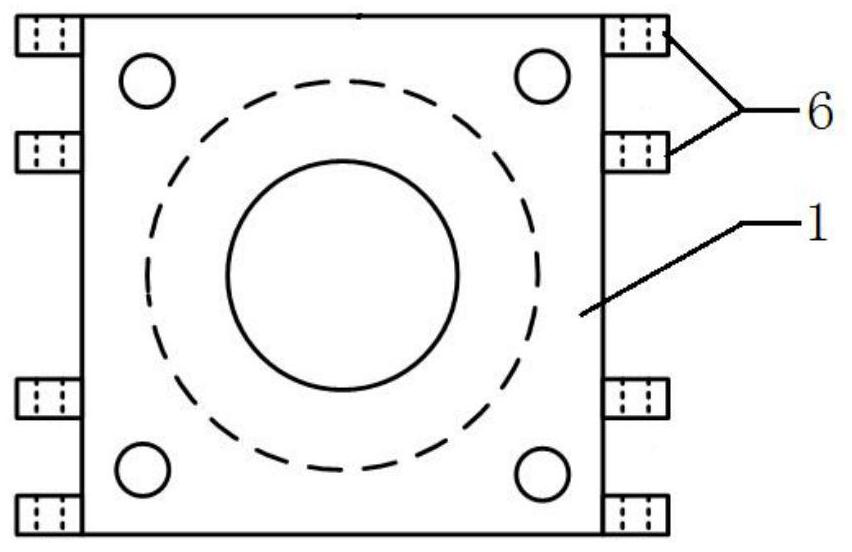
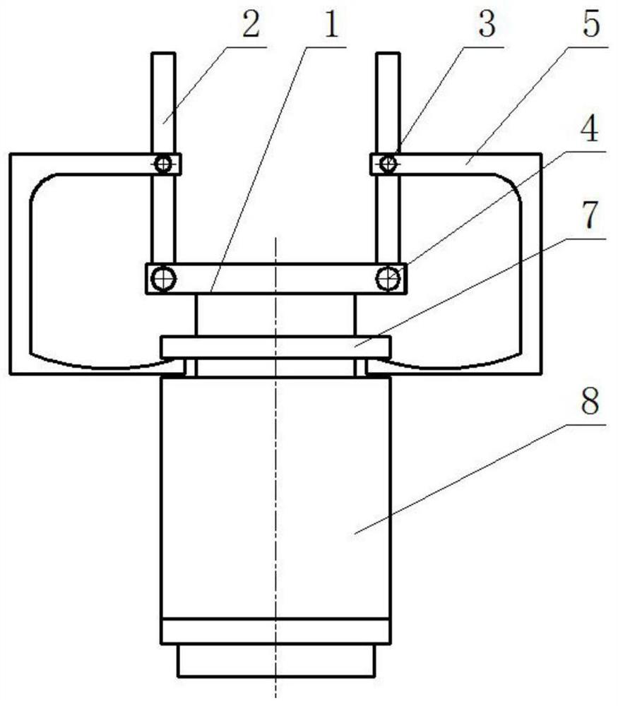
[0018] A quick-change flange for a transformer dehumidifier, including a connecting flange 1, a pull rod 2, and a pull hook 5. A vent hole is formed in the center of the connecting flange, and the vent hole is coaxial and equal in diameter to the vent hole of the dehumidifier flange. Four pull rods are hinged symmetrically at the four corners of the connecting flange, and a pull hook is hinged on each pull rod. The connecting flange is connected with the flange of the moisture absorber through a pull hook, and the hook end of the pull hook is hung in the flange hole on the bottom surface of the flange 7 of the moisture absorber.

[0019] The hinged installation method of the connecting flange and the...


PUM


Abstract

The invention relates to a quick replacement flange of a transformer moisture absorber, which includes a connecting flange, a pull rod and a pull hook. A vent hole is formed in the center of the connecting flange, and the vent hole is coaxial and equal in diameter to the vent hole of the flange of the moisture absorber. Four pull rods are symmetrically hinged at the four corners of the connecting flange, and a pull hook is hinged on each pull rod. The connecting flange and the dehumidifier flange are connected by a pull hook, and the hook end of the pull hook is hung on the flange hole of the dehydrating absorber flange. Inside. The quick replacement flange of the transformer dehumidifier solves the complicated problem of operation and maintenance personnel replacing the transformer dehumidifier, effectively improves the replacement efficiency of the transformer dehumidifier, and avoids breaking the glass cover of the dehumidifier and disassembling the dehumidifier caused by the replacement of the transformer dehumidifier. Flanges or transformers are screwed down, and even personnel get an electric shock.

Description

technical field [0001] The invention belongs to the field of substation operation, and relates to a transformer connection flange, in particular to a quick replacement flange of a transformer moisture absorber. Background technique [0002] The transformer dehumidifier is used to remove and dry the sundries and moisture in the air entering the transformer (or transformer) oil conservator due to the change of transformer oil temperature, so as to ensure the insulation strength of transformer oil. When the transformer is heated and expands, the excess air inside the transformer is exhaled; when the transformer oil temperature decreases and contracts, the outside air is sucked in. When the outside air is sucked in, the transformer oil in the oil storage box filters the outside air, and then the silica gel absorbs the unfiltered water, so that the transformer oil in the transformer is not invaded by the water in the outside air, so that the water content remains constant. withi...

Claims


Application Information

Patent Timeline
Patent Type & Authority Patents(China)
IPC IPC(8): H01F27/14
CPCH01F27/14
Inventor 于永生贾建华邹志文孙艳凤陈广锡张恒肖建超王序辰辛晓虎王海超何少川王骞
Owner STATE GRID TIANJIN ELECTRIC POWER
Learn More