MEMS Gyroscope with Overload Protection Mechanism
A micro-electromechanical gyroscope and overload protection technology, which is applied to gyroscope/steering sensing equipment, gyro effect for speed measurement, instruments, etc., can solve the problems of increased drive spring stress, secondary impact of the structure, and reduced device overload resistance. , to achieve the effect of improving stiffness and anti-overload capacity
- Summary
- Abstract
- Description
- Claims
- Application Information
AI Technical Summary
Problems solved by technology
Method used
Image

Examples
Embodiment 1
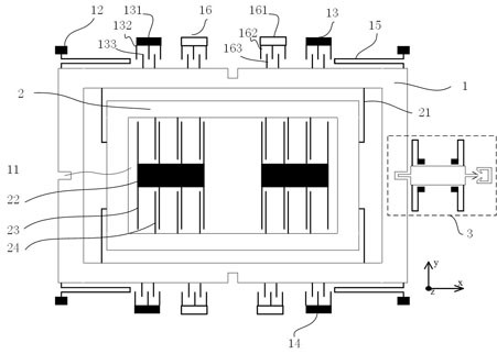
[0059] Such as figure 1 As shown, the MEMS gyroscope with an overload protection mechanism includes a gyroscope body and a control block 3, and the gyroscope
[0060] The instrument body is provided with a limit slot 11, and the control block 3 is provided with a limit latch 311 adapted to the limit slot 11; when the gyroscope body is in working condition, the limit latch 311 and the limit The position slot 11 has no overlap (that is, the limit latch 311 is separated from the limit slot 11, and the limit latch 311 is located outside the limit slot 11); when the gyroscope body is in a non-working state, the limit latch 311 and the limit There is overlap in the position slot 11 (that is, a part of the structure of the limit latch 311 is located in the limit slot 11); There are gaps between the walls.
[0061] When the gyroscope body is in the non-working state, the limit latch 311 on the control block 3 overlaps with the limit groove 11 on the gyroscope body by a certain lengt...
Embodiment 2
[0063] On the basis of the first embodiment, this embodiment also includes: figure 1 As shown, the gyroscope body includes a driving mass 1, a gyroscope anchor point 12, a first comb tooth electrostatic driver 13, a second comb tooth electrostatic driver 14, a detection mass 2, a driving spring 15 and a detection spring 21, the driving The mass 1 is provided with a limiting groove 11, the gyroscope anchor point 12 is connected to the driving mass 1 via a driving spring 14, and the first comb tooth electrostatic driver 13 is used to drive the driving mass 1 along the first axis (y-axis ) forward movement, the second comb tooth electrostatic driver 14 is used to drive the driving mass 1 to move backward along the first axis (y-axis), and the detection mass 2 is connected to the driving mass 1 via a detection spring 21 .
[0064] exist figure 1 Among them, two gyroscope anchor points 12 are provided on the first side of the driving mass 1, and two gyroscope anchor points 12 are ...
Embodiment 3
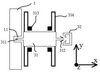
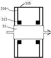
[0069] On the basis of the first embodiment, this implementation also includes: figure 2 As shown, the control block 3 includes a control block mass 31, a deck 32, a control block anchor point 313 and a control block spring 314, the control block mass 31 is located between the driving mass 1 and the deck 32, and the control block The mass 31 is provided with a limit latch 311 and a buckle 312 adapted to the clamp 32 , and the control block anchor point 313 is connected to the control block mass 31 via a control block spring 314 .
[0070] The mass 31 of the control block is connected to the anchor point 313 of the control block through the spring 314 of the control block, so that the control block 3 and the gyroscope body remain relatively stationary in the non-working state.
[0071] When the gyroscope body is in the non-working state, a part of the structure of the limit latch 311 is located in the limit groove 11 (that is, the limit latch 311 overlaps with the limit groove...
PUM
 Abstract
Description
Claims
Application Information
 - R&D
- Intellectual Property
- Life Sciences
- Materials
- Tech Scout
- Unparalleled Data Quality
- Higher Quality Content
- 60% Fewer Hallucinations
Browse by: Latest US Patents, China's latest patents, Technical Efficacy Thesaurus, Application Domain, Technology Topic, Popular Technical Reports.
© 2025 PatSnap. All rights reserved.Legal|Privacy policy|Modern Slavery Act Transparency Statement|Sitemap|About US| Contact US: help@patsnap.com