Animal feeding trough

A technology for feeding troughs and livestock, applied in the field of breeding tools, can solve the problems of inconvenient cleaning of livestock feeding troughs, and achieve the effects of reducing the breeding of flies and bacteria, improving histocompatibility, and having a simple structure.

Pending Publication Date: 2019-01-15
杭州渔森农业技术开发有限公司
View PDF0 Cites 4 Cited by
  • Summary
  • Abstract
  • Description
  • Claims
  • Application Information

AI Technical Summary

Problems solved by technology

[0005] The purpose of the present invention is to solve the technical problem of inconvenient cleaning in the livestock trough of the prior art, and provide a livestock trough to solve the deficiencies of the prior art

Method used


Image

  • Animal feeding trough
  • Animal feeding trough
  • Animal feeding trough

Examples


Embodiment 1

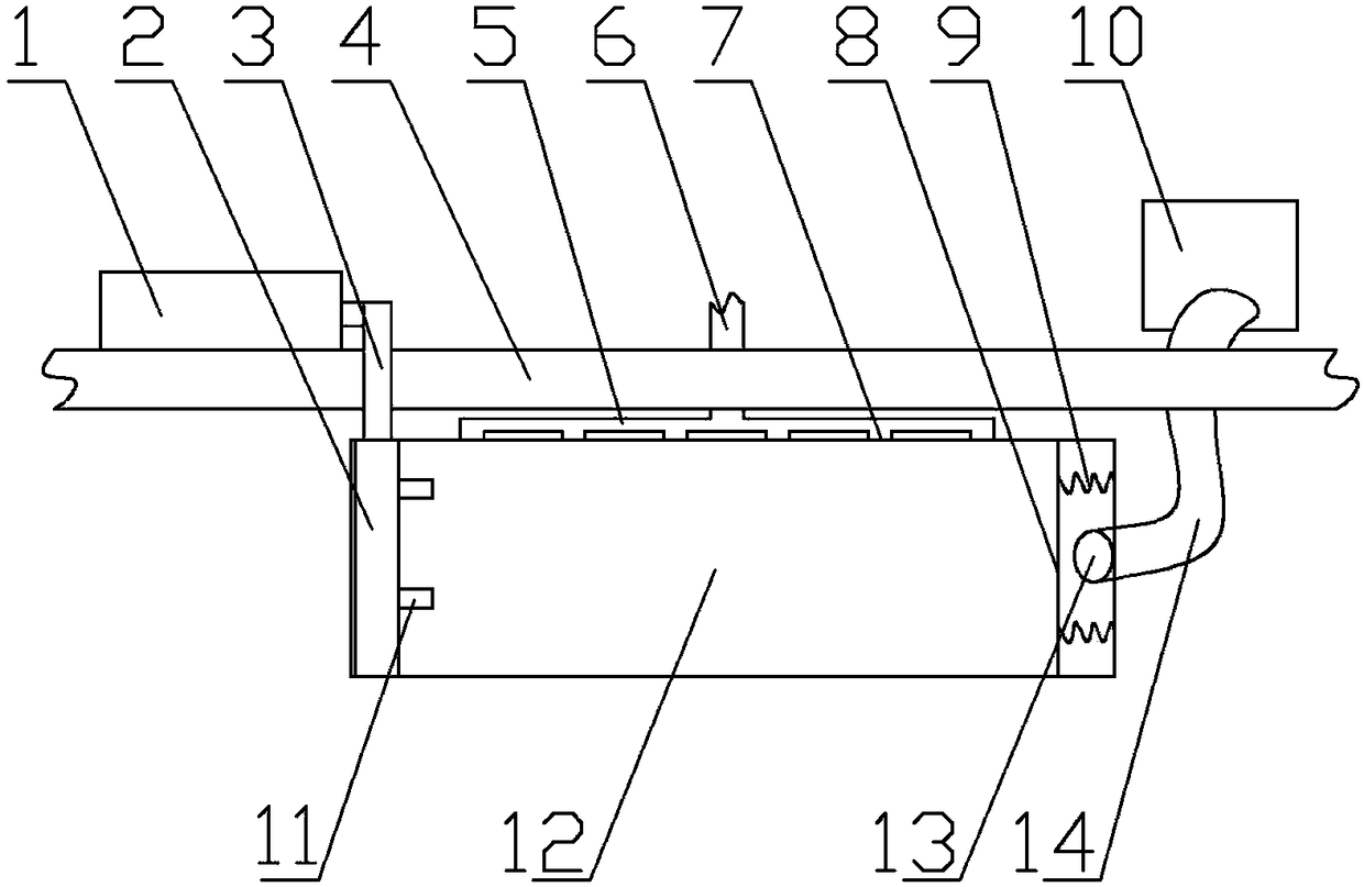
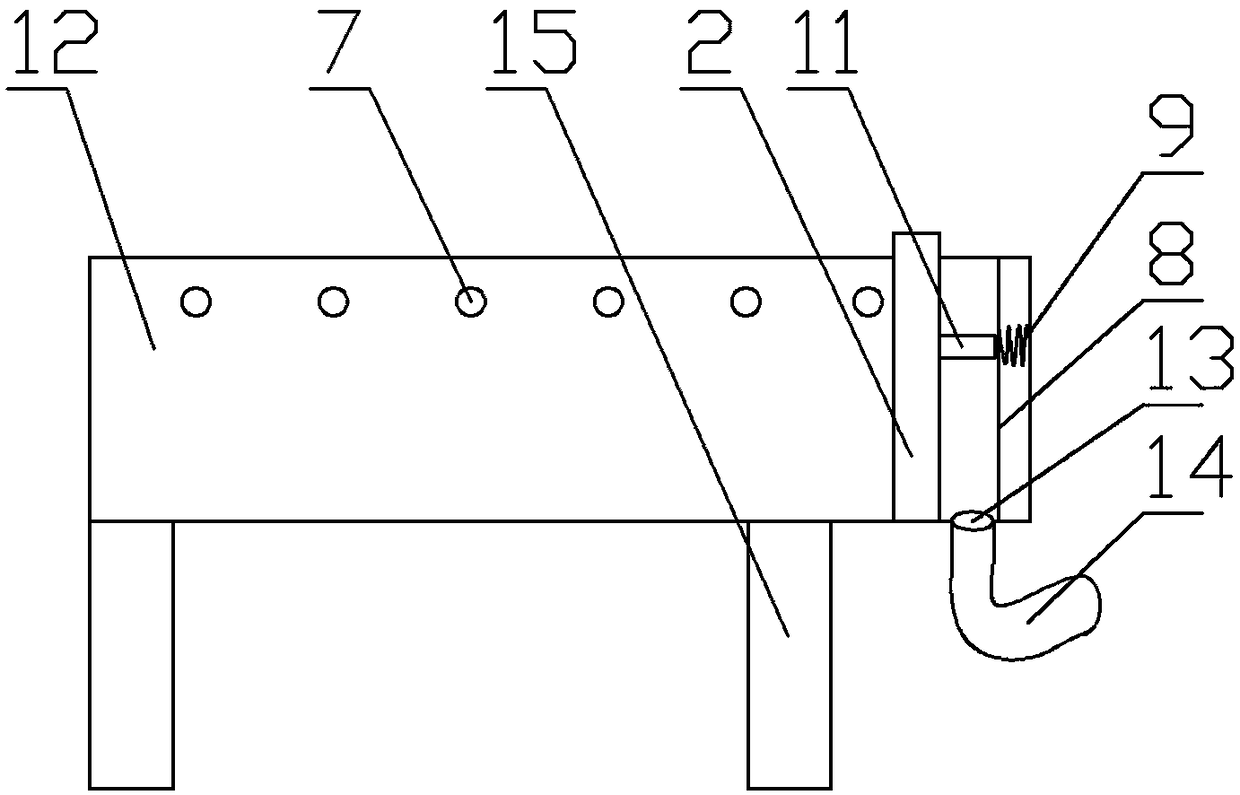
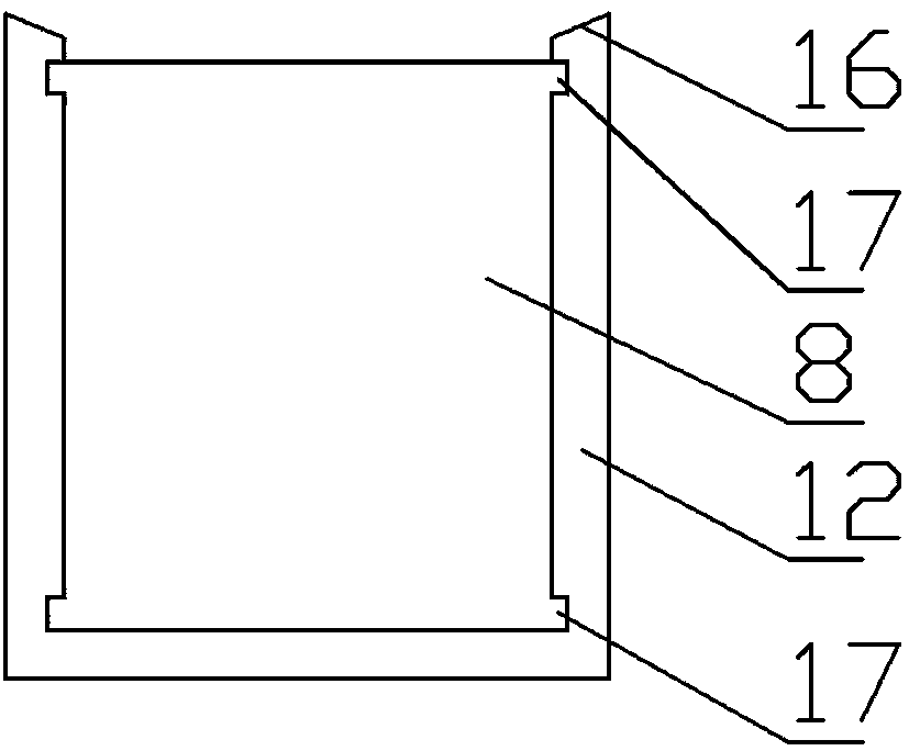
[0026] according to Figure 1-Figure 3 , a livestock trough, which includes a stainless steel tank 12 close to the fence 4 on one side; legs 15 are provided below the tank 12; a push plate 2 is provided at one end of the tank; the push plate 2 Fitted with the inner wall of the tank body 12; the push plate 2 is provided with a connecting rod 3 extending into the outside of the fence; the fence 4 is provided with a pushing device 1 connected with the connecting rod 3; A collection hole 13 is provided at the bottom of one end; a collection box 10 is provided on the outside of the fence; the collection hole 13 is connected to the collection box 10 through a connecting pipe 14; a vertically divided baffle plate 8 is provided in front of the collection hole 13 ; The baffle plate 8 is slidingly connected to the tank body 12; a spring 9 is provided between the end of the baffle plate and the tank body; the push plate 2 is provided with a push rod 11 corresponding to the baffle plate 8...

Embodiment 2

[0038] As another invention point of the present invention, the present invention also improves the push plate material, improves its mechanical properties and aging resistance, and has certain antibacterial properties; the push plate is prepared according to the following steps:

[0039] 1) Mix polypropylene resin, phenolic resin, ethylene-vinyl acetate copolymer, polycarbonate, triallyl cyanurate and oleic acid amide in a mass ratio of 50:10:5:3:2:1 Evenly, add to the internal mixer, the internal mixing time is 10min, the internal mixing temperature is 85°C, and component A is obtained;

[0040] 2) Mix nano-titanium dioxide and nano-silver evenly at a mass ratio of 2:1 to obtain a mixture, then add it to twice the weight of deionized water, stir well, and then add hexamethylcyclotrisiloxane with the same mass as nano-silver , heated to 80°C, under the condition of heat preservation, ultrasonic dispersion treatment for 10min, and then naturally cooled to room temperature to o...

Embodiment 3

[0044] Taking Example 2 as an example, various aspects of performance of the push plate material have been detected:

[0045] Among them, a control group is set up, in which,

[0046] Control group 1: without adding component B, the rest are the same as in Example 2;

[0047] Control group 2: No component C was added, and the rest were the same as in Example 2.

[0048] The tensile strength, elongation at break, and yellowing index were tested respectively, as shown in Table 1:

[0049] Table 1

[0050] group

[0051] Conclusion: By adding a certain proportion and type of auxiliary materials, the tensile strength, elongation at break and anti-aging ability can be significantly improved.


PUM


Abstract

The invention discloses an animal feeding trough. The animal feeding trough comprises a stainless steel trough body close to one side fence; supporting legs are arranged below the trough body; one endinside the trough body is provided with a pushing plate; the pushing plate is fit with the inner wall of the trough body; a connecting rod extending outside the fence is arranged on the pushing plate; the fence is provided with a pushing device connected with the connecting rod; the bottom of one end of the trough body is provided with a collecting hole; a collecting box is arranged outside the fence; the collecting hole is connected with the collecting box through a connecting pipe; a vertical baffle is arranged in front of the collecting hole; the baffle and the trough body are in sliding connection; a spring is arranged between the baffle and the end part of the trough body; and the pushing plate is provided with an ejecting rod corresponding to the baffle. The structure is simple andreasonable; after animal feeding is completed, the residue in the feeding trough is quickly cleaned through the pushing plate, breeding of flies and bacteria is reduced, and the technical problem of inconvenient cleaning of the animal feeding trough in the prior art can be effectively solved.

Description

technical field [0001] The invention belongs to the technical field of breeding utensils, and in particular relates to a livestock trough. Background technique [0002] Livestock troughs are used to feed grain and forage, etc. The previous livestock troughs were mainly marble troughs, but now they are mostly made of stainless steel. [0003] The stainless steel food trough comprises a bar-shaped groove for holding food materials, the bottom surface of the groove is rectangular or arc-shaped, and the bottom of the groove is provided with supporting legs. This stainless steel trough has a simple structure and is durable, but it is inconvenient to clean, and the deposited feed residue is easy to rot and breed flies and bacteria. [0004] At present, some manufacturers leave an opening at the end of the trough, so that it can be cleaned directly from one side to the end, but before each cleaning, a collection box must be placed, and then cleaned one by one with tools, which is ...

Claims


Application Information

Patent Timeline
IPC IPC(8): A01K5/01C08L23/12C08L61/06C08L23/08C08L69/00C08K3/22C08K3/08C08K9/06C08K9/02C08K3/34B08B9/087B29D7/00
CPCA01K5/01C08L23/12B08B9/087B29D7/00C08K2003/0806C08K2003/2241C08K2201/011C08L2205/035C08L61/06C08L23/08C08L69/00C08K3/22C08K3/08C08K9/06C08K9/02C08K3/346
Inventor 应玉生吴顺元应勇根应天元蔡国祥
Owner 杭州渔森农业技术开发有限公司
Why Eureka
Try Eureka