
Engine stop/start control device

一种起动控制装置、发动机停止的技术,应用在发动机控制、发动机的起动、发动机用电动机起动等方向,能够解决再起动变差、无法确保空气量等问题

Inactive Publication Date: 2019-01-11
DENSO CORP
View PDF11 Cites 0 Cited by
  • Summary
  • Abstract
  • Description
  • Claims
  • Application Information

AI Technical Summary

Problems solved by technology

However, in the above cases, when the engine is restarted, a sufficient amount of air required for combustion cannot be ensured, resulting in poor restart

Method used


Image

  • Engine stop/start control device
  • Engine stop/start control device
  • Engine stop/start control device

Examples


Embodiment Construction

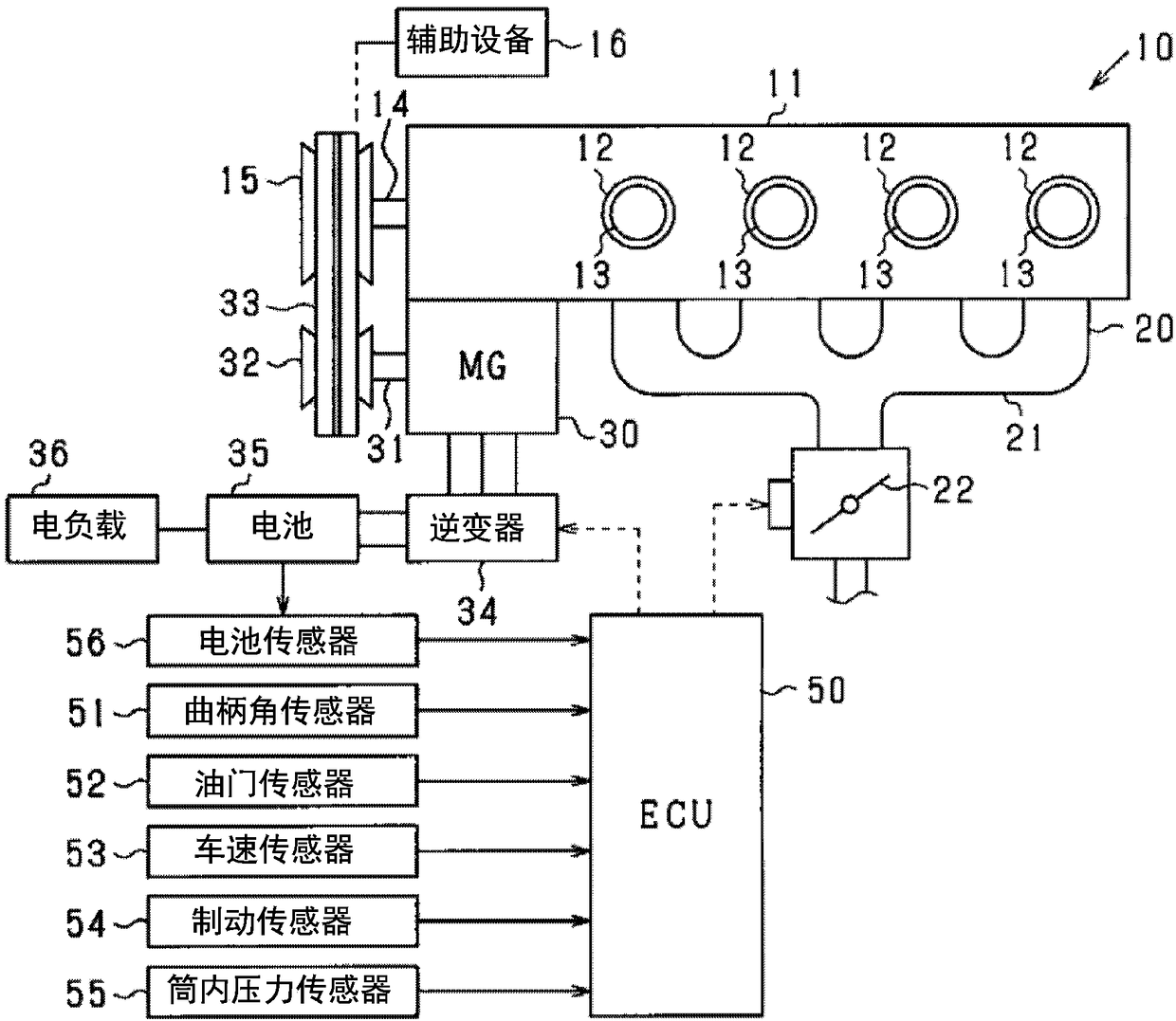
[0035] Hereinafter, embodiments embodying the present invention will be described based on the drawings. This embodiment embodies a control system for an engine mounted on a vehicle. In the control system described above, an electronic control unit (hereinafter referred to as ECU) is used as a center to control the operating state of the engine and the like. The overall schematic diagram of the system is figure 1 shown.

[0036] exist figure 1 In the vehicle 10 shown, the engine 11 is driven by combustion of fuel such as gasoline, and is a four-stroke engine that repeatedly performs each cycle of intake, compression, expansion, and exhaust. The engine 11 has four cylinders (gas cylinders) 12 , and a piston 13 is housed in each cylinder 12 . Furthermore, the engine 11 appropriately includes a fuel injection valve (not shown), an ignition device (not shown), and the like. In addition, in this embodiment, an engine with four cylinders is shown, but the number of cylinders of...


PUM


Abstract

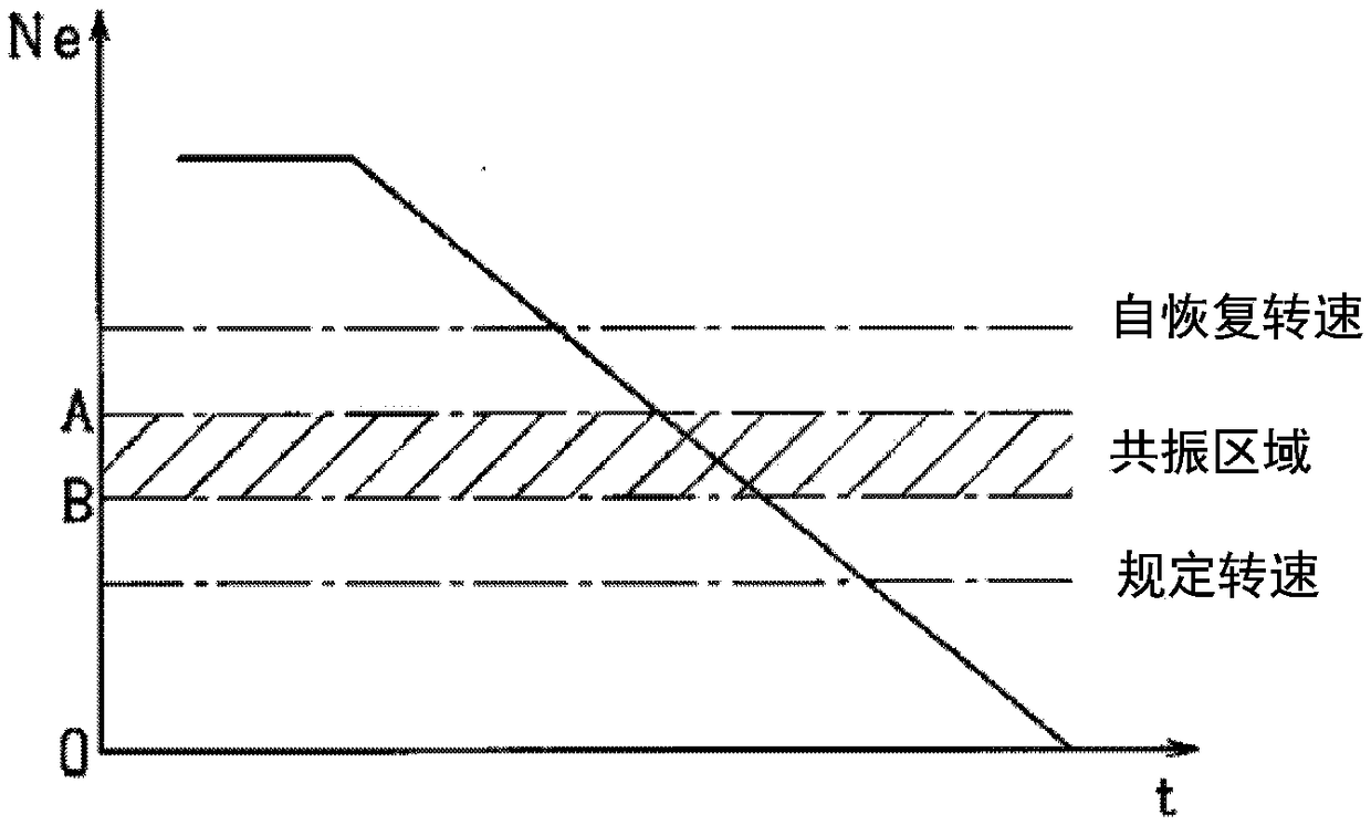
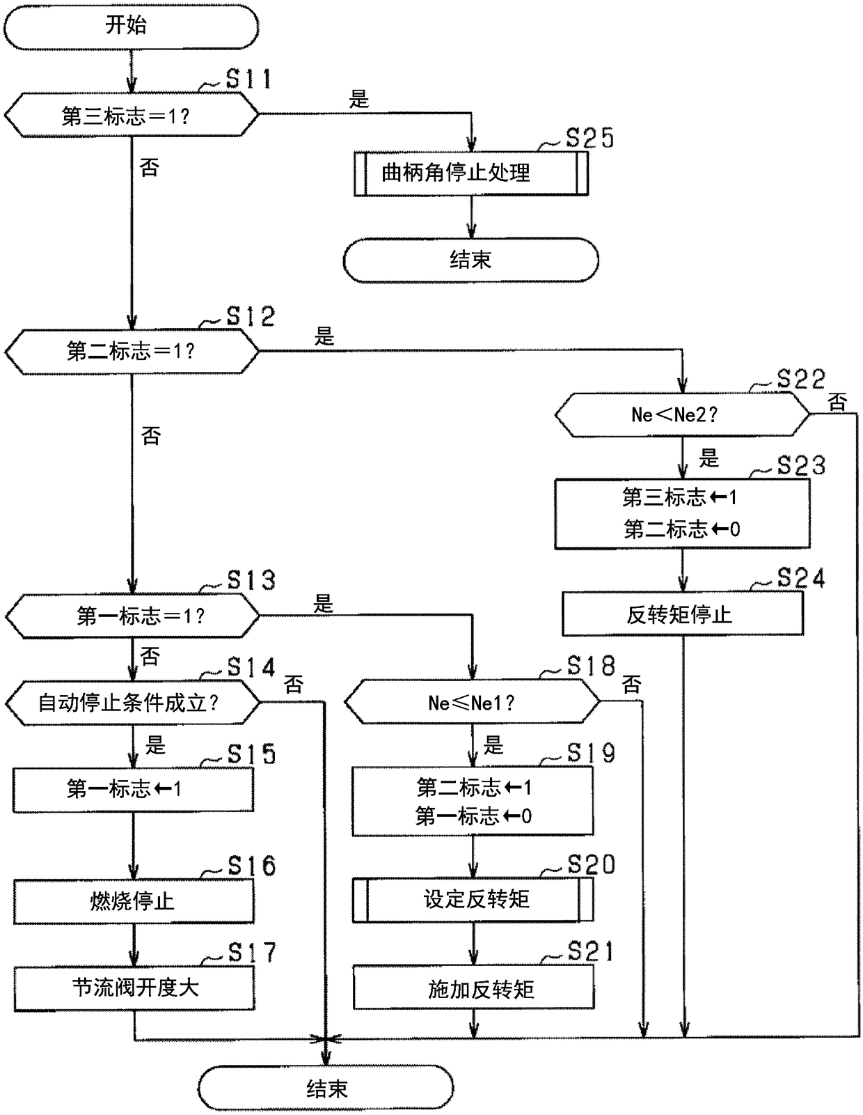
After the combustion of an engine (11) has stopped and during a speed reduction period when the engine speed reduces to zero, an ECU (50) opens a throttle valve (22) to a greater degree than during idle rotation of the engine (11). In addition, the ECU (50) determines, during the speed reduction period, whether or not the engine speed is in a prescribed rotation speed range including at least a resonance range for the engine (11) and, if a determination is made that the engine speed is within the prescribed rotation speed range, implements speed reduction whereby the speed of reduction in theengine speed is temporarily increased.

Description

[0001] References to related applications [0002] This application is based on the Japanese patent application number 2016-094757 for which it applied on May 10, 2016, and uses the description content here. technical field [0003] The invention relates to an engine stop and start control device. Background technique [0004] Conventionally, there is known a technique of automatically stopping the engine when a predetermined automatic stop condition is satisfied, and then executing so-called idle stop control when a predetermined restart condition is satisfied. [0005] When the engine is automatically stopped, the opening of the throttle valve is smaller than the specified opening, restricting the supply of air to the cylinder. However, in the above case, when the engine is restarted, a sufficient amount of air required for combustion cannot be secured, resulting in poor restart. [0006] In the technique described in Patent Document 1, when the engine is automatically s...

Claims


Application Information

Patent Timeline
Patent Type & Authority Applications(China)
IPC IPC(8): F02D29/02F02D41/04F02D43/00F02D45/00
CPCF02D41/04F02D43/00F02D45/00F02D29/02F02D41/042B60W10/06F02N2200/022F02N11/0844F02D41/0002F02N11/04F02D41/062F02N11/0814B60W2510/0638F02N11/0818
Inventor 星野将吾
Owner DENSO CORP
Learn More