DIM dimming circuit to avoid OVP mistriggering

A dimming circuit and false triggering technology, applied in the field of LED dimming, can solve the problems of OVP false triggering and inconvenient use.

Pending Publication Date: 2019-01-11
无锡恒芯微科技有限公司
View PDF0 Cites 0 Cited by
  • Summary
  • Abstract
  • Description
  • Claims
  • Application Information

AI Technical Summary

Problems solved by technology

[0002] Most of the DIM dimming function chips that appear on the market directly adjust the sampling voltage of the ISEN port. Such a circuit is relatively simple to implement, but the current practical application requires a non-isolated LED drive circuit with OVP function. At present, the OVP function on the market is realized by detecting the demagnetization time of the system, such as figure 1 As shown, the demagnetization time is directly related to the current of the LED, the inductor current, and the sampling voltage of the ISEN port. Adjusting the sampling voltage of the ISEN port to realize the DIM dimming function will cause false triggering of the OVP, which is inconvenient to use.

Method used


Image

  • DIM dimming circuit to avoid OVP mistriggering
  • DIM dimming circuit to avoid OVP mistriggering
  • DIM dimming circuit to avoid OVP mistriggering

Examples


Embodiment Construction

[0015] The technical solutions of the present invention will be described in further detail below through specific implementation methods.

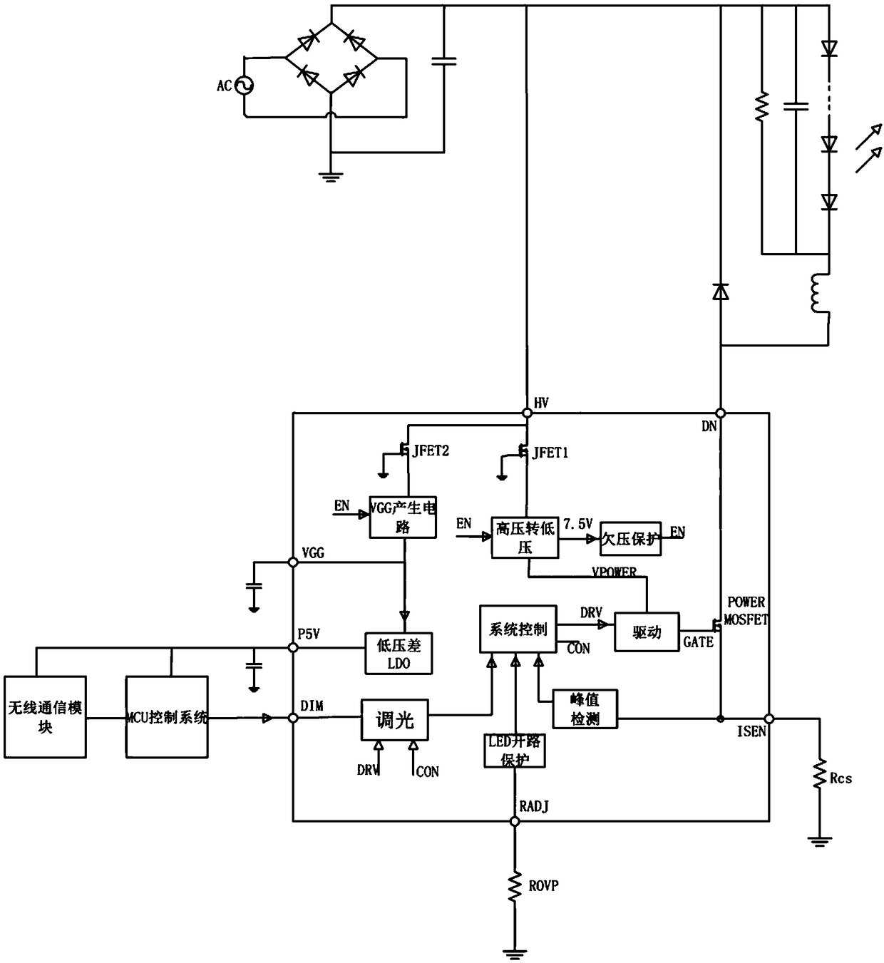
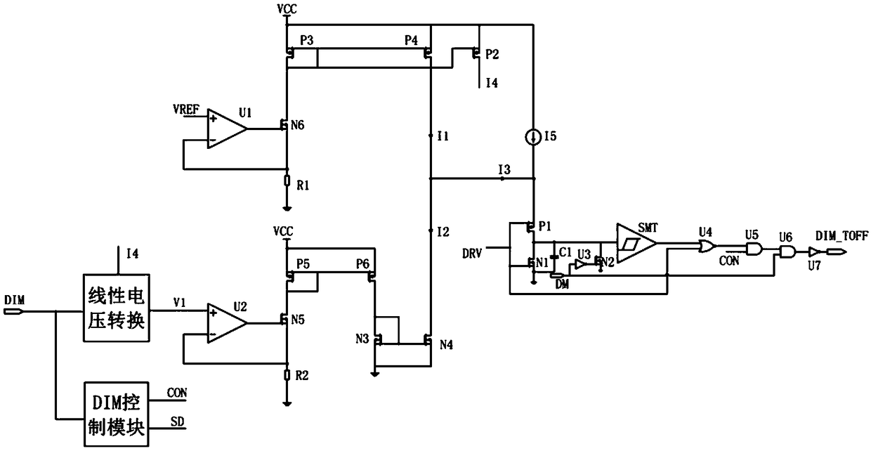
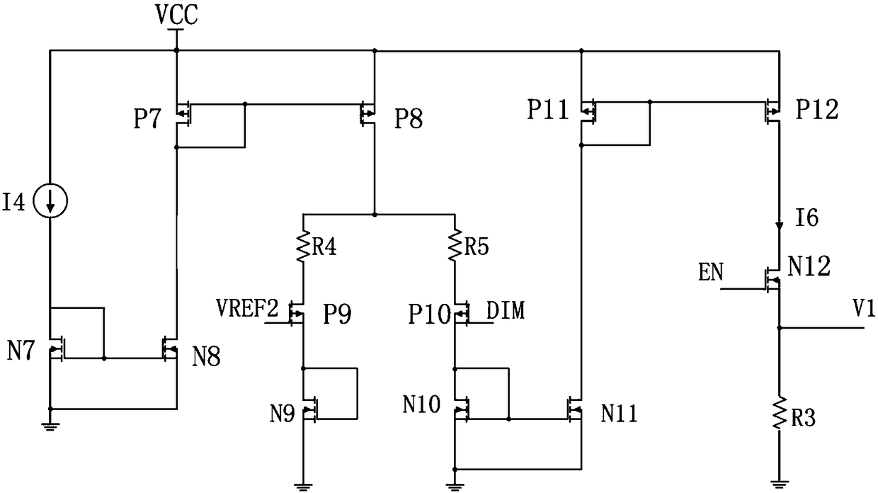
[0016] Such as figure 1 , figure 2 , image 3 and Figure 4 As shown, a DIM dimming circuit that avoids OVP false triggering, the input end of the linear voltage conversion circuit and the input end of the DIM control module respectively receive the DIM dimming signal, the DIM control module outputs the CON signal and the SD signal, and the linear voltage conversion circuit The output terminal of the operational amplifier U2 is connected to the non-inverting input terminal of the operational amplifier U2, the output terminal of the operational amplifier U2 is connected to the gate of the MOS transistor N5, the source of the MOS transistor N5 is grounded through the resistor R2, and the inverting input terminal of the operational amplifier U2 is connected to the gate of the MOS transistor N5 The source, the drain of the MOS transistor ...


PUM


Abstract

The invention provides a DIM dimming circuit for avoiding OVP mistriggering. By increasing demagnetization time, the current of the LED becomes small, the analog dimming function is realized, the ISENsampling voltage is kept unchanged, and the peak current of the IL is kept unchanged, so that the OVP function is not affected. The DIM dimming circuit avoiding OVP mistriggering has the advantages of scientific design, strong practicability, simple structure and strong stability.

Description

technical field [0001] The invention relates to the field of LED dimming, in particular to a DIM dimming circuit for avoiding OVP false triggering. Background technique [0002] Most of the DIM dimming function chips that appear on the market directly adjust the sampling voltage of the ISEN port. Such a circuit is relatively simple to implement, but the current practical application requires a non-isolated LED drive circuit with OVP function. At present, the OVP function on the market is realized by detecting the demagnetization time of the system, such as figure 1 As shown, the demagnetization time is directly related to the current of the LED, the inductor current, and the sampling voltage of the ISEN port. Adjusting the sampling voltage of the ISEN port to realize the DIM dimming function will cause false triggering of the OVP, which is inconvenient to use. [0003] In order to solve the above existing problems, people have been seeking an ideal technical solution. Con...

Claims


Application Information

Patent Timeline
IPC IPC(8): H05B33/08H05B44/00
CPCH05B45/00
Inventor 吴建良顾南昌吴洁
Owner 无锡恒芯微科技有限公司
Why Eureka
Try Eureka