Tool wear image stitching method and tool life prediction method

A tool wear and image technology, which is applied to the details of image stitching, image enhancement, image analysis, etc., can solve the problems of workpiece scrapping and life prediction.

Active Publication Date: 2019-01-11
HARBIN UNIV OF SCI & TECH
View PDF7 Cites 6 Cited by
  • Summary
  • Abstract
  • Description
  • Claims
  • Application Information

AI Technical Summary

Problems solved by technology

[0005] In order to solve the problem that the existing tool wear detection technology can only be manually disassembled and detected after the tool is moved, and does not have life prediction, it is easy to cause the workpiece to be scrapped

Method used


Image

  • Tool wear image stitching method and tool life prediction method
  • Tool wear image stitching method and tool life prediction method
  • Tool wear image stitching method and tool life prediction method

Examples


specific Embodiment approach 1

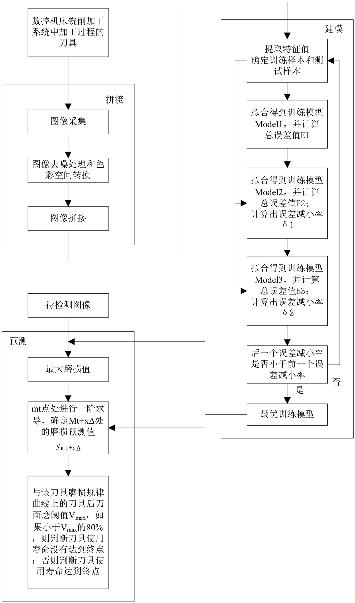
[0062] This embodiment is a method for mosaicing tool wear images, including the following steps:

[0063] Step 1. Collect images:

[0064] Take each edge face and bottom face (cutter face) of the tool as the object, and collect the wear image A of the bottom face of the tool 0 , and the wear image of the blade surface is collected continuously along each blade surface Ensure that two adjacent images have overlapping areas; q is the serial number of each blade surface, q=1,2,...,Q; Q is the total number of blade surfaces; the subscript "w" is the number of images collected along the blade surface sequence number;

[0065] The blade surface of the tool is helical. When collecting each blade surface, the image acquisition device needs to spirally rise along the blade surface to continuously collect images of the blade surface, and ensure that images with overlapping areas are continuously collected along the blade surface; The sequence number of is marked as w;

[0066] Tak...

specific Embodiment approach 2

[0073] The specific process of step 3 is as follows:

[0074] According to the H, S, V values ​​​​of the HSV color space, a Cartesian coordinate system is established, and the space vector modulus is taken As the feature value, select two adjacent images that need to be spliced, calculate the space vector modulo P for each pixel, and use the area with the same P value in the two images as the area to be fused (corresponding to the overlapped area in the two images part), the four vertices of the area to be fused are recorded as A, B, C, D and A', B', C', D' in the two images, and the eight vertices are determined in the Cartesian coordinate system Coordinates, and determine the vector representations of AB and A'B' respectively, which are recorded as AB(m, n) and A'B'(e, f), and use point A as the reference point to establish the translation between A and A' Transformation equation g(x, y) = g 1 (x+x A -x A’ ,y+y A -y A’ );

[0075] Among them, x and y respectively rep...

specific Embodiment approach 3

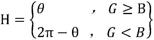
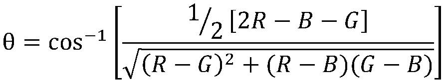
[0079] The specific process of converting the R, G, and B values ​​of the RGB color space into the H, S, and V values ​​of the HSV color space described in step 2 is as follows:

[0080]

[0081]

[0082]

[0083]

[0084] Among them, H, S, and V are the H, S, and V values ​​of the HSV color space, respectively.


PUM


Abstract

The invention relates to a tool wear image stitching method and a tool life prediction method, which relate to the tool life prediction field to solve the problem that the existing tool wear detectiontechnology can only be disassembled manually after the tool is moved, without life prediction, it is easy to lead to the scrap of the workpiece. The invention takes each edge surface and bottom surface of the cutter as the object, collects the bottom surface wear image of the cutter, and converts the image processed by denoising into RGB color space, and further converts the image into HSV colorspace. The space vector module is taken as the eigenvalue, the image is fused through the translation equation and rigid matrix model to form the stitching image. Secondly, the depth learning engine is used to train the stitching image signal based on the stitching image, and the optimal depth learning model is generated by smoothing the solution process and error reduction rate analysis. Then thewear trend can be predicted by the data in the database to achieve the function of tool life prediction. The present invention is used for tool life prediction.

Description

technical field [0001] The invention relates to the field of tool life prediction, in particular to a tool life prediction method. Background technique [0002] In the environment of Industry 4.0 and Intelligent Manufacturing 2025, the intelligent manufacturing industry of cutting tools is developing rapidly. The degree of tool wear during CNC machine tool processing directly determines the quality of the processed workpiece. [0003] Due to the time-varying, unstable and environmental factors in the processing process that affect the continuous wear of the tool, the tool wear process has the characteristics of real-time and uncertainty. Therefore, the actual monitoring of the tool wear state has become a development in the field of tool wear detection. trend. [0004] The traditional tool wear detection technology is limited to the monitoring of the tool wear state, that is, the tool wear degree can be monitored at this time through the tool wear detection technology, and ...

Claims


Application Information

Patent Timeline
Patent Type & Authority Applications(China)
IPC IPC(8): G06T3/00G06T7/00G05B23/02
CPCG05B23/0283G06T7/0004G06T2207/20221G06T2207/30108G06T2207/20081G06T2200/32G06T2207/10024G06T2207/10016G06T3/14Y02P90/30
Inventor 吴雪峰牟澳磊
Owner HARBIN UNIV OF SCI & TECH
Why Eureka
Try Eureka