
display device

A display device and scanning line technology, applied in the direction of instruments, nonlinear optics, optics, etc., can solve the problems of rising cost of timing processing chips, a large drop in panel penetration rate, difficult debugging and maintenance, etc., and the solution is simple and easy to implement , Good visual compensation effect, uniform brightness effect

Active Publication Date: 2021-02-26
CHONGQING HKC OPTOELECTRONICS TECH CO LTD +1
View PDF7 Cites 0 Cited by
  • Summary
  • Abstract
  • Description
  • Claims
  • Application Information

AI Technical Summary

Problems solved by technology

[0006] Since the liquid crystal is controlled by a directional light valve, it is relatively easy to cause large viewing angle deviation, that is, when viewed at a relatively oblique angle, there will be color deviation.
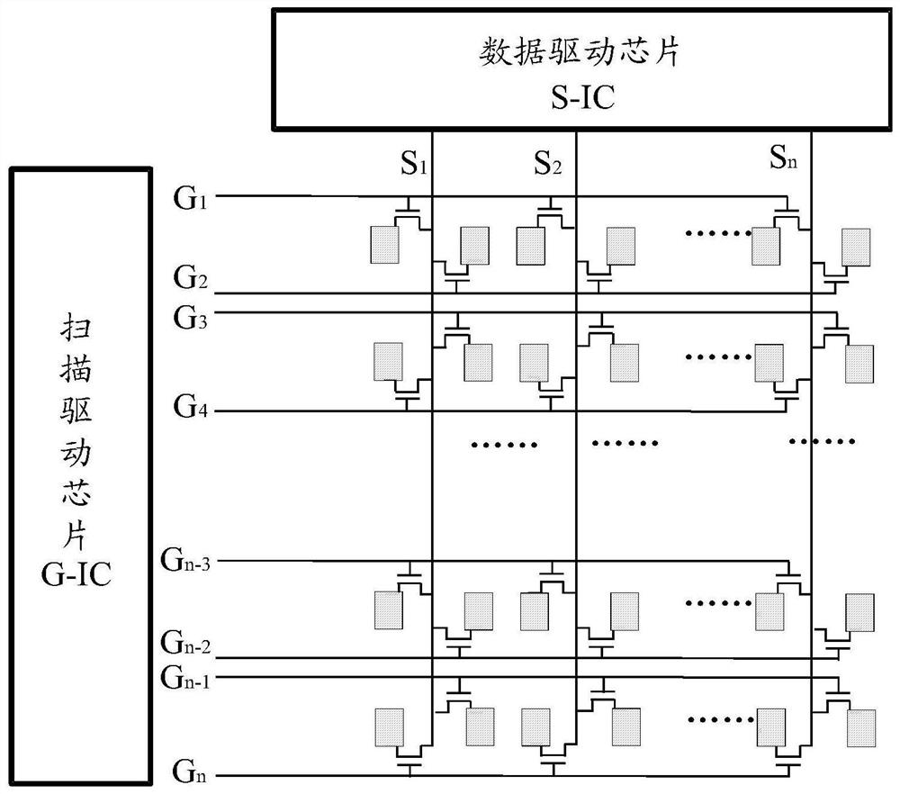
like figure 1 As shown, the brightness of any two adjacent pixels of the existing display device is the same. At present, in order to improve this phenomenon, there are two methods. One is to adopt the original one pixel ( Pixel) is divided into main pixel (main pixel) and sub pixel (sub pixel), dimming the brightness of sub pixel, but this will cause the penetration rate of the panel to drop a lot; another method is to use mathematics inside the timing processing chip The special algorithm is used to design bright and dark data for adjacent pixels, which has little effect on the transmittance of the LCD panel, but the algorithm is complex, debugging and maintenance are not easy, and the cost of timing processing chips will increase

Method used


Image

  • display device
  • display device
  • display device

Examples


Embodiment Construction

[0024] The following will clearly and completely describe the technical solutions in the embodiments of the present invention with reference to the accompanying drawings in the embodiments of the present invention. Obviously, the described embodiments are only part of the embodiments of the present invention, not all of them. Based on the embodiments of the present invention, all other embodiments obtained by persons of ordinary skill in the art without creative efforts fall within the protection scope of the present invention.

[0025] It should be noted that if there is a directional indication (such as up, down, left, right, front, back...) in the embodiment of the present invention, the directional indication is only used to explain the position in a certain posture (as shown in the accompanying drawing). If the specific posture changes, the directional indication will also change accordingly.

[0026] In addition, if there are descriptions involving "first", "second" and ...


PUM


Abstract

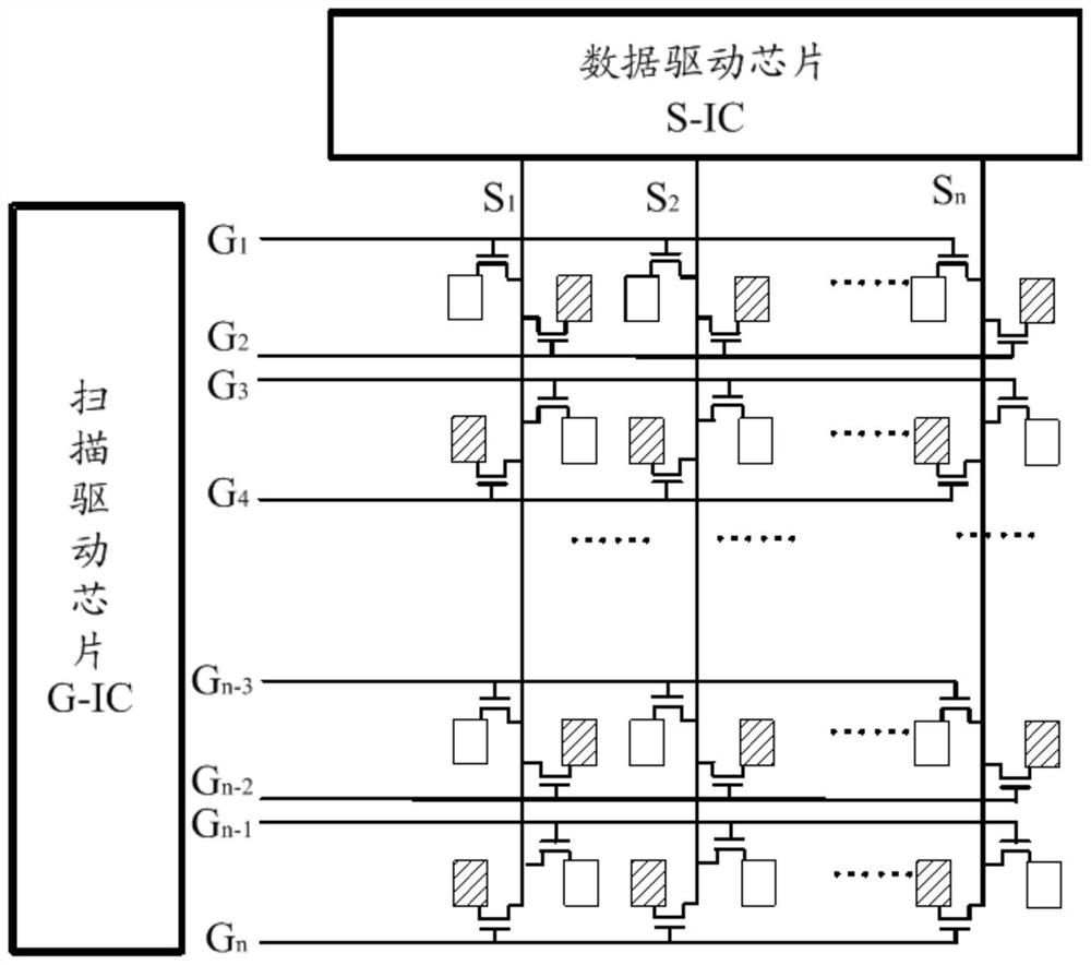
The invention discloses a display device, the display device has a plurality of pixels, the plurality of pixels are distributed along a matrix of multiple rows and columns at intervals, and the pixels distributed along the rows include a plurality of pixels distributed at intervals on odd rows Pixels and a plurality of pixels distributed at intervals on even lines, the brightness of the pixels on the odd lines is different from the brightness of the pixels on the even lines. Since the brightness of the pixels on the odd-numbered rows of the display device proposed by the present application is different from the brightness of the pixels on the even-numbered rows, that is, the brightness of the pixels on the odd-numbered rows is greater than or smaller than the brightness of the pixels on the even-numbered rows, therefore, high The light emitted by the brightness pixel can be mixed with the light emitted by the low brightness pixel, so as to achieve a better visual compensation effect, thereby making the brightness of the display device uniform and consistent, and avoiding the problem of color shift of the display device under different viewing angles.

Description

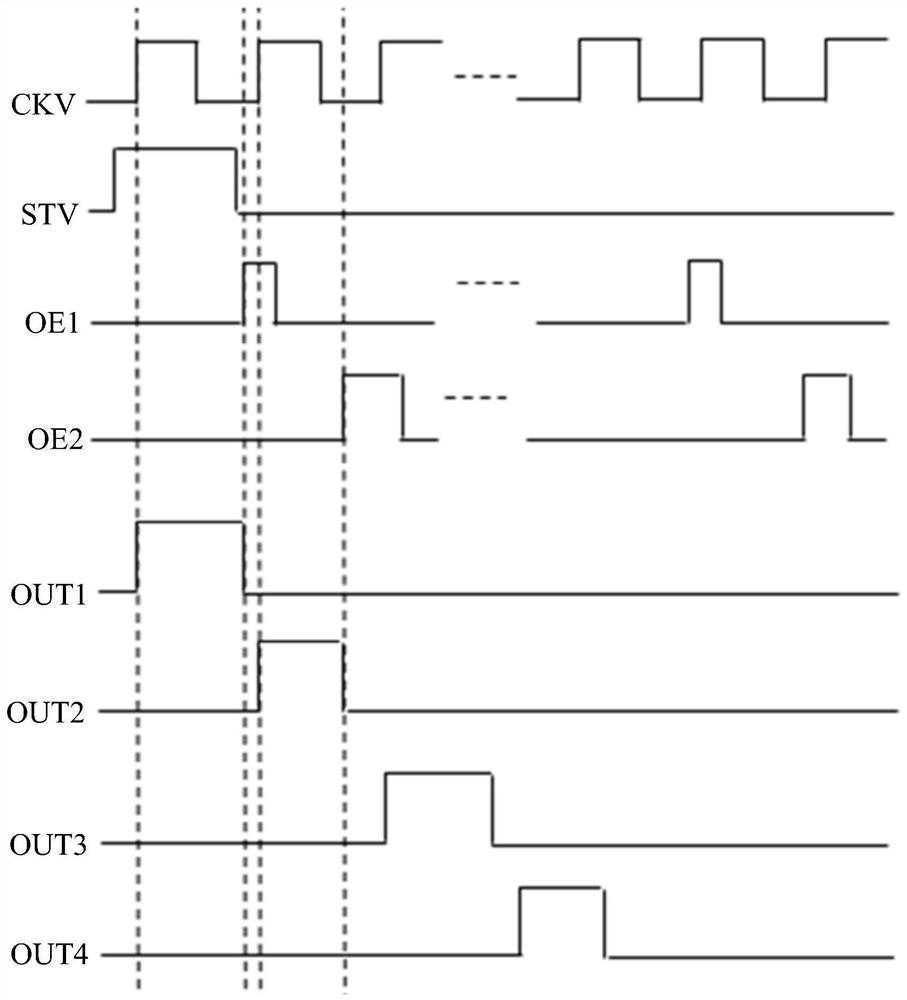
technical field [0001] The invention relates to the field of displays, in particular to a display device. Background technique [0002] The driving circuit system of the liquid crystal display includes: a scanning driving integrated circuit, also known as a gate driving integrated circuit (Gate Driver Integrated Circuit, G-IC); and a data driving integrated circuit, also known as a source driving integrated circuit (Source Driver IC, S-IC). [0003] The liquid crystal display is driven by row-by-row scanning, that is, one row is turned on sequentially, and each time a row is turned on, all column data signal lines transmit data to the pixels of the row. According to the number of rows turned on at a certain moment and the input of corresponding pixel signals, the pixel driving structure can be divided into 1G1D and 2G2D. [0004] The 1G1D structure is the conventional driving method of pixels, that is, only one row is turned on at a certain time, and all columns transmit d...

Claims


Application Information

Patent Timeline
Patent Type & Authority Patents(China)
IPC IPC(8): G02F1/1333G02F1/1343G02F1/1362G02F1/1368
CPCG02F1/1333G02F1/134309G02F1/136286G02F1/1368
Inventor 王明良
Owner CHONGQING HKC OPTOELECTRONICS TECH CO LTD
Learn More