
Complex system radar full-pulse digital generation method based on headmost pulse

A generation method and pre-pulse technology, applied in the field of system simulation, can solve problems such as large amount of calculation, poor fidelity of cross pulses, complex sorting algorithm, etc., and achieve high simulation fidelity, fast operation speed, and strong scalability Effect

Active Publication Date: 2019-01-11
SOUTHWEST CHINA RES INST OF ELECTRONICS EQUIP
View PDF9 Cites 2 Cited by
  • Summary
  • Abstract
  • Description
  • Claims
  • Application Information

AI Technical Summary

Problems solved by technology

The performance of this modeling method is between the characteristic parameter method and the pulse sequence method. Since the radar signals in the group are all regarded as conventional pulses, the sorting algorithm is relatively simple to implement, but due to the limitation of the simulation beat (difficult to reach the microsecond level) , unable to support full-pulse simulation of complex system signals such as frequency agility and frequency hopping
[0004] In addition, most of the existing radar signal waveform modeling methods do not consider the influence of the radar signal space transmission delay on the full pulse generation, resulting in poor fidelity of the generated cross pulses
[0005] Therefore, in the current research on full-pulse digital generation of multiple radars with different densities in complex systems, there are still problems such as complex sorting algorithms, large calculations, and poor fidelity, which require continuous exploration and research

Method used


Image

  • Complex system radar full-pulse digital generation method based on headmost pulse
  • Complex system radar full-pulse digital generation method based on headmost pulse
  • Complex system radar full-pulse digital generation method based on headmost pulse

Examples


Embodiment Construction

[0027] All features disclosed in this specification, or steps in all methods or processes disclosed, may be combined in any manner, except for mutually exclusive features and / or steps.

[0028]Any feature disclosed in this specification, unless specifically stated, can be replaced by other alternative features that are equivalent or have similar purposes. That is, unless expressly stated otherwise, each feature is one example only of a series of equivalent or similar features.

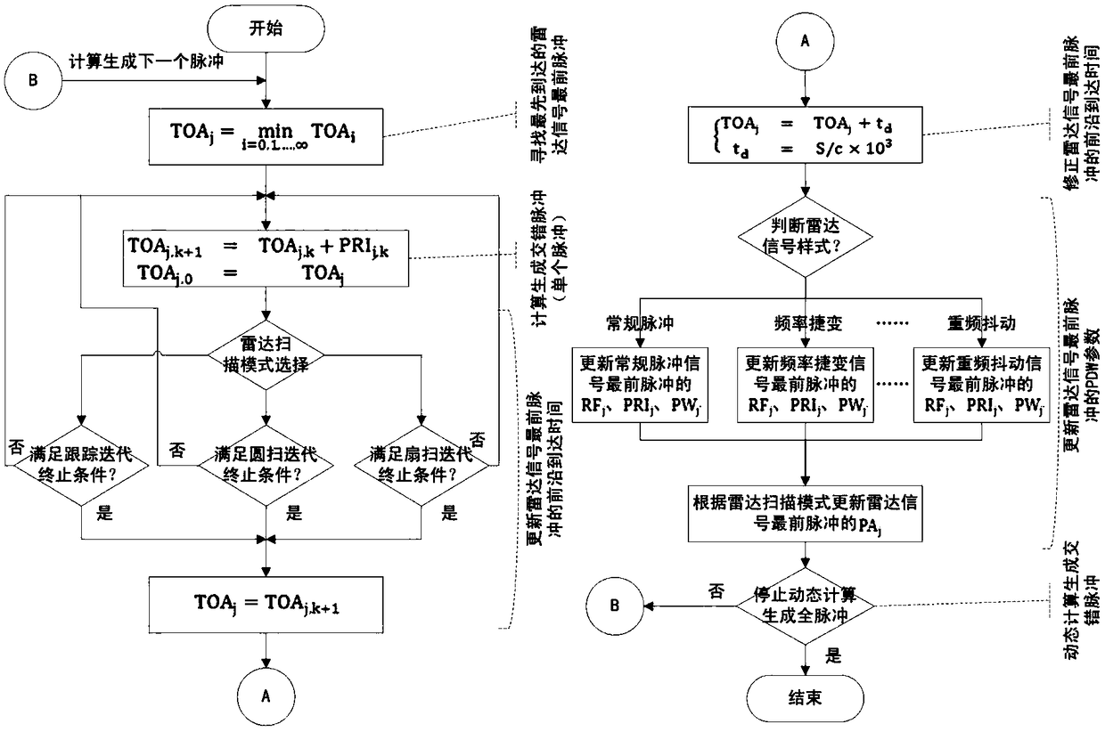
[0029] Such as figure 1 , the complex system radar full-pulse digital generation method of the most advanced pulse, specifically including the following process:

[0030] Step 1, define the first arrival pulse in the radar signal pulse sequence as the first pulse of the radar signal, and find the first arrival pulse of the radar signal in the simulated scene;

[0031] Preferably, the specific process of step 1 is: step 11, defining the first arrival pulse in the radar signal pulse sequence as the fir...


PUM


Abstract

The invention relates to the technical field of system simulation, and discloses a complex system radar full-pulse digital generation method based on the headmost pulse. The complex system radar fullpulse digital generation method comprises the following process that the first arrival pulse in a radar signal pulse sequence is defined as the radar signal headmost pulse, and the first arrival radarsignal headmost pulse in a simulation scene is found; description word parameters of the first arrival radar signal headmost pulse are preserved into a to-be-output staggered pulse list, and the staggered pulse is calculated and generated; the leading-edge arrival time of the radar signal headmost pulse is updated; the leading-edge arrival time of the radar signal headmost pulse is corrected aiming at the radar signal transmission delay time; PDW parameters of the radar signal headmost pulse are updated; and dynamic calculating is conducted to complete full-pulse digital generation. The influences of radar antenna scanning on whether the pulse is generated or not and the pulse amplitude, and the influences of electromagnetic wave space transmission delay on the pulse arrival time are comprehensively balanced, and the characteristics of high extendibility, high simulation fidelity, high operation speed and the like are achieved.

Description

technical field [0001] The invention relates to the technical field of system simulation, in particular to a method for generating full-pulse digital generation of complex system radar based on the first pulse. Background technique [0002] Due to the complexity of the electromagnetic environment of the modern battlefield and the dependence of electronic countermeasure equipment training on the environment, it is necessary to realize the simulation of radar signal scenarios with complex systems and different densities. At present, there are two main methods of radar signal waveform modeling: characteristic parameter method and pulse sequence method. Among them, the characteristic parameter method is to describe all the pulses generated by each radar signal in each simulation beat through characteristic parameters according to the radar signal pattern. This modeling method has super real-time advantages in calculation, but it can only support the functional level Simulation,...

Claims


Application Information

Patent Timeline
Patent Type & Authority Applications(China)
IPC IPC(8): G01S7/40
CPCG01S7/4052
Inventor 姚金宝肖鹏赵亮刘小亮
Owner SOUTHWEST CHINA RES INST OF ELECTRONICS EQUIP
Learn More