
A chiral optical device

An optical device and chiral technology, which is applied in scientific instruments, instruments, and material analysis through optical means, can solve the problems of inconspicuous circular dichroism signals and poor detection results, and achieve enhanced circular dichroism Effect

Active Publication Date: 2021-10-15
XIAN CREATION KEJI CO LTD
View PDF8 Cites 0 Cited by
  • Summary
  • Abstract
  • Description
  • Claims
  • Application Information

AI Technical Summary

Problems solved by technology

[0004] In the research of chiral structure in the prior art, by designing a two-dimensional metal thin film chiral structure, it has been possible to realize the modulation of the polarization characteristics of the beam or to detect the circular dichroism of the chiral substance, but when the detected signal itself is relatively weak, The obtained circular dichroism signal is not obvious, that is, the detection effect is not very good

Method used


Image

  • A chiral optical device
  • A chiral optical device
  • A chiral optical device

Examples


Embodiment 1

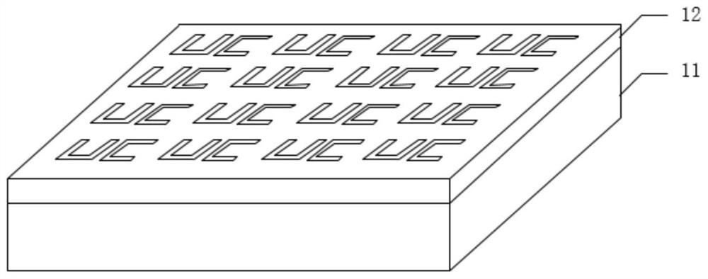
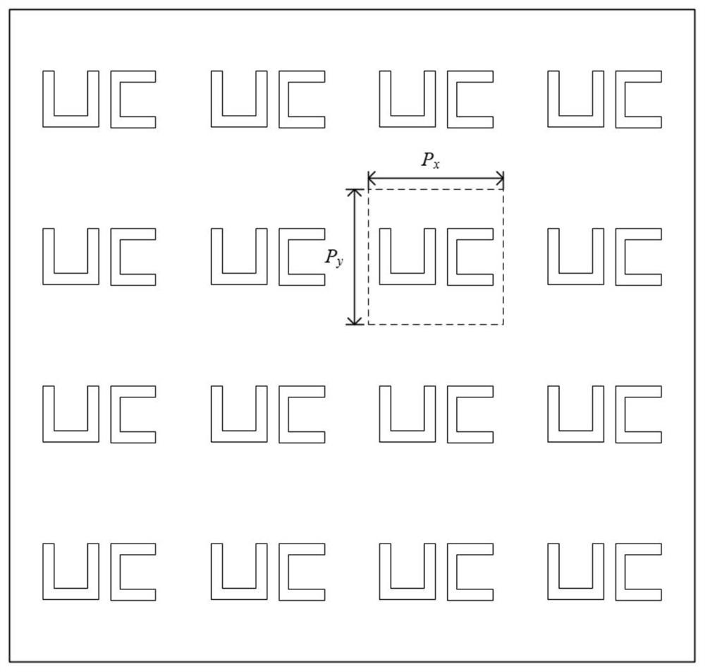
[0028] See figure 1 and figure 2 , figure 1 is a schematic diagram of a three-dimensional structure of a chiral optical device according to an embodiment of the present invention, figure 2 It is a schematic structural diagram of a metal film of a chiral optical device according to an embodiment of the present invention; the chiral optical device includes: a substrate 11, a metal film 12 on the substrate 11;

[0029] The material of the substrate 11 is a material with high transmittance for the used light band, such as silicon dioxide, quartz, and the like.

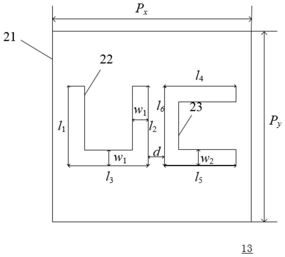
[0030] The metal film 12 is provided with several chiral structural units 13 that run through the upper and lower surfaces of the metal film 12 and are arranged in an array. The chiral structural units 13 include: basic U-shaped slits 22 arranged adjacently And reinforced C-shaped seam 23.

[0031] In the metal film 12, the chiral structural units 13 are uniformly arranged in the horizontal and vertical directions of...

Embodiment 2

[0042] See Figure 4 , Figure 4It is a schematic diagram of the principle of circular dichroism generated by a chiral optical device provided by an embodiment of the present invention. When a beam of left circularly polarized light (left circularly polarized, LCP) is incident from the front of the chiral optical device at an incident angle, after passing through the chiral optical device, the transmittance of the received left circularly polarized light is T--, When a beam of right circularly polarized (RCP) is incident from the front of the chiral optical device at the same incident angle, after passing through the chiral optical device, the transmittance of the received right circularly polarized light is T++, where The mark "--" means left-handed polarized light, and "++" means right-handed polarized light, then the circular dichroism of the chiral structural unit can be expressed as:

[0043] CD=T++-T--

[0044] The transmittance of left-handed polarized light and righ...


PUM

PropertyMeasurementUnit
thicknessaaaaaaaaaa

Abstract

The invention relates to a chiral optical device, comprising: a substrate and a metal film on the substrate; wherein, the metal film is provided with several chiral optical devices that run through the upper and lower surfaces of the metal film and are arranged in an array. A chiral structural unit, the chiral structural unit includes: a basic U-shaped slit and a reinforced C-shaped slit adjacently arranged. In the chiral optical device of the invention, the circular dichroism of the chiral optical device is significantly enhanced through a metal film having a basic U-shaped slit and an enhanced C-shaped slit.

Description

technical field [0001] The invention belongs to the field of optical devices, in particular to a chiral optical device. Background technique [0002] Chirality refers to the property that a structure and its mirror image cannot overlap. Chiral structures are ubiquitous in nature, such as proteins, glycosylation, and DNA and other biomacromolecules. Chirality plays a key role in biochemistry and life evolution. According to its structural characteristics, chirality can be divided into: intrinsic chirality and extrinsic chirality. Intrinsic chirality refers to the chirality of the structure itself, and extrinsic chirality refers to the chirality formed by the structure and incident light. [0003] Circular Dichroism (CD) is a very important method to study chiral compounds. In the study of chiral molecular asymmetry, when left-handed circularly polarized light and right-handed circularly polarized light are incident, chiral materials will exhibit different effective refracti...

Claims


Application Information

Patent Timeline
Patent Type & Authority Patents(China)
IPC IPC(8): G01N21/19
CPCG01N21/19
Inventor 尹晓雪
Owner XIAN CREATION KEJI CO LTD
Learn More