Biaxial tension test calibration debugging method based on crossed test piece

A technology of bidirectional stretching and debugging method, which is applied in the direction of applying stable tension/pressure to test the strength of materials, measuring devices, instruments, etc., and can solve problems such as inability to quantitatively calibrate and debug, wrong result phenomena, and bending moment torque in the test piece. , to achieve the effect of excellent calibration, simple equipment and easy implementation

Active Publication Date: 2019-01-11
SOUTHEAST UNIV
View PDF12 Cites 3 Cited by
  • Summary
  • Abstract
  • Description
  • Claims
  • Application Information

AI Technical Summary

Problems solved by technology

Whether it is calibration and debugging or coordinated loading, the fundamental purpose is to ensure the accuracy of the test. At present, the accuracy of the testing machine and the clamping of the test piece are mainly used to ensure the accuracy. This method does not fully consider the difficulties of biaxial loading, nor It is impossible to perform quantitative calibration and debugging, and it is easy to cause additional in-plane bending moment or torque on the test piece
Fo

Method used


Image

  • Biaxial tension test calibration debugging method based on crossed test piece
  • Biaxial tension test calibration debugging method based on crossed test piece
  • Biaxial tension test calibration debugging method based on crossed test piece

Examples


Embodiment 1

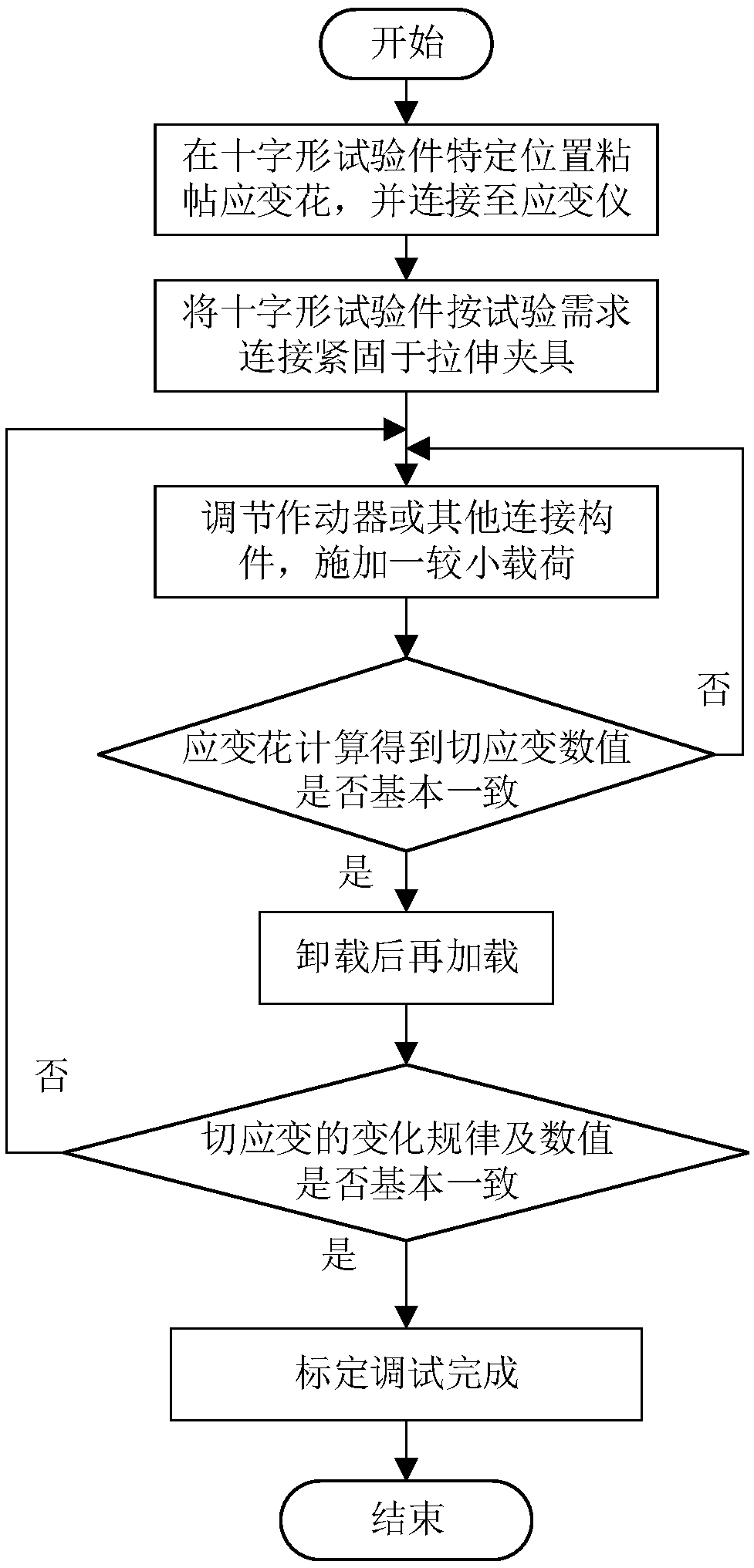
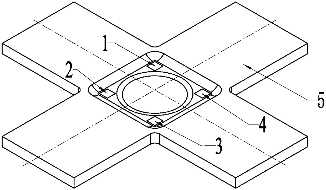
[0027] refer to Figure 1 ~ Figure 3 , according to one embodiment of the present invention, a kind of bidirectional tensile test calibration debugging method based on cross-shaped test piece, comprises the following steps:

[0028] (1) Paste strain rosettes 1 to 4 symmetrically on the area where the cross-shaped test piece 5 bears the two-way tensile force, and leave the central area, that is, the two-way stress area, and connect the strain rosettes 1 to 4 to the strain gauges for adjustment. Connect and fasten the cross-shaped test piece 5 to the special fixture as required;

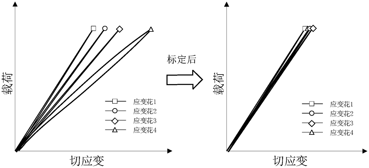
[0029] (2) Under quasi-static loading with equal proportion load, that is, the tensile force along different directions remains the same at each moment of loading. At this time, the cross-shaped test piece 5 bears the same tensile force along the directions of the four arms. Ideally, the shear strain values ​​calculated by strain rosettes 1 to 4 should be the same and very small, that is, less than 50...

Embodiment 2

[0036] refer to Figure 4 , the difference from Example 1 is that for another type of cross-shaped test piece 5, the positions where the strain gauges 1-4 are pasted are different, but they are still symmetrically arranged and the distance from its center is the same. At this time, only It is only necessary to adjust the actuator or connecting member in the corresponding direction.


PUM


Abstract

The invention discloses a biaxial tension test calibration debugging method based on a crossed test piece. The biaxial tension test calibration debugging method comprises the following steps: pastinga strain rosette to a specific position of the crossed test piece, and carrying out calculation by virtue of the strain rosette to obtain a shearing strain at the pasted position; regulating an actuator or other connecting members so that the value change rule and the value of the shearing strain are basically consistent within an elastic range, and in such a case, considering that the test piecehas a relatively small additional load; and carrying out loading after clearing data according to a general mechanical test on the basis to finish calibration. The debugging method is simple in adopted equipment, easy to implement, capable of achieving a relatively good calibration effect and suitable for calibration debugging before dynamic tests such as a quasi-static test or a fatigue test.

Description

technical field [0001] The invention belongs to the technical field of physical performance testing of engineering materials, and in particular relates to a calibration debugging method for bidirectional tensile tests based on a cross-shaped test piece. Background technique [0002] The mechanical properties of materials under complex stress states will show complexity. Compared with uniaxial tests, biaxial tests can be used to obtain more realistic mechanical parameters or responses of materials. Generally speaking, there are many loading forms of biaxial test, among which the most intuitive one is biaxial tensile test based on cross-shaped specimen. [0003] At present, there is no standard test piece and no standard test procedure for this kind of bidirectional tensile test. Compared with uniaxial test, the difficulty of biaxial loading lies in the coordinated control of forces in two directions, which also puts forward higher requirements for calibration and debugging b...

Claims


Application Information

Patent Timeline
IPC IPC(8): G01N3/08G01N3/02
CPCG01N3/02G01N3/08
Inventor 费庆国柳友志张大海刘璟泽何顶顶何俊增
Owner SOUTHEAST UNIV
Why Eureka
Try Eureka