
Device and method for performing ultimate drawing test of anchor plate under plane strain condition

A technology of plane strain and pull test, applied in the direction of measuring device, using stable tension/pressure test material strength, instrument, etc., can solve the problem of unable to study the pull-out of anchor plate, and achieve stable pull-out angle Effect

Pending Publication Date: 2019-01-11
SHANDONG UNIV
View PDF1 Cites 8 Cited by
  • Summary
  • Abstract
  • Description
  • Claims
  • Application Information

AI Technical Summary

Problems solved by technology

The inventor believes that the anchoring plate of the disclosed device is placed vertically, and it is impossible to study the pulling situation of the anchoring plate at different angles

Method used


Image

  • Device and method for performing ultimate drawing test of anchor plate under plane strain condition
  • Device and method for performing ultimate drawing test of anchor plate under plane strain condition

Examples


Embodiment 1

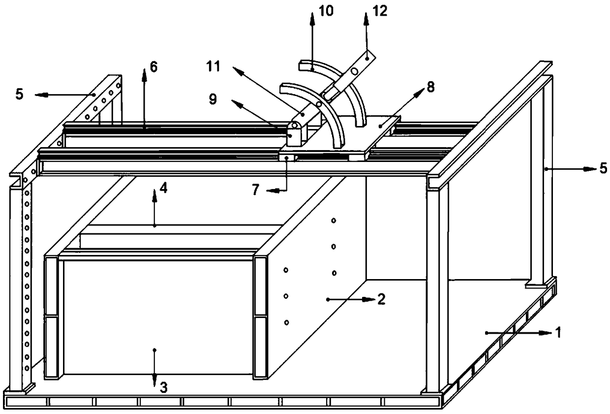
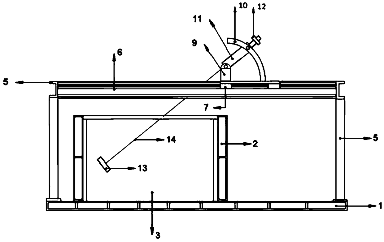
[0037] Such as figure 1 As shown, an anchor plate ultimate pullout test device under plane strain conditions includes a base 1, a test soil box, a main support, a retaining plate 4, an anchor plate 13, an anchor rod 14, a displacement device and a loading device, The base 1 is provided with a test soil box, and the soil body is filled in the test soil box; one side of the test soil box adopts plexiglass 3 panels to realize transparency, and the test soil box has a non-transparent side wall Drill holes so that the anchor rod 14 can pass through; the soil retaining plate 4 is located in the soil box and can be moved to respectively realize the test device for the front fracture surface of the anchor plate 13 and the ultimate bearing capacity; the main support end The part is connected with the displacement device. Described main support adopts steel support 5, as figure 1 As shown in , the steel bracket 5 includes four vertical columns and two horizontal columns distributed in...

Embodiment 2

[0053] The difference between Embodiment 2 and Embodiment 1 is that both ends of the slide rail 6 are fixed to the columns, mainly to realize the horizontal loading of the anchor plate 13 .


PUM


Abstract

The invention discloses a device for performing an ultimate drawing test of an anchor plate under a plane strain condition. The device is characterized by comprising a test soil box, a main support, asoil baffle, an anchor rod, a displacement device and a loading device; the test soil box is filled with a soil body; one side of the test soil box is transparent, so that the observation can be facilitated; a non-transparent side wall of the test soil box is punched for the anchor rod to penetrate through; the soil baffle is arranged in the soil box, and can be moved to realize test devices forthe front fracture surface and the ultimate bearing capacity of the anchor plate; the end part of the main support is connected with the displacement device; and the displacement device is connected with the loading device. The invention provides a test model device which can be used for researching the ultimate bearing capacity of the anchor plate in the ultimate drawing test by accurately controlling different angles under the plane strain condition, and the development law of the front soil body fracture surface of the anchor plate.

Description

technical field [0001] The invention belongs to the field of geotechnical engineering, and in particular relates to an ultimate pulling test device and method of an anchor plate under the condition of plane strain. Background technique [0002] With the construction of a large number of railways, highways, water conservancy, mines and other facilities, especially in the construction of hills and mountainous areas, the number of slopes excavated and filled in human engineering activities will increase, and the height will increase . Due to complex geological conditions, coupled with the increasing scale of human transformation of nature, improper design and construction methods, frequent accidents that cause deformation and disasters after excavation of high slopes, this not only increases project investment, but also delays the construction period and returns to the operation period. Leave a hidden danger. Slope and landslide disasters threaten the safety of human life, pr...

Claims


Application Information

Patent Timeline
IPC IPC(8): G01N3/02G01N3/10
CPCG01N3/02G01N3/10G01N2203/0048G01N2203/0017
Inventor 张宏博李为传宋彦颉岳红亚宋修广杨振宇
Owner SHANDONG UNIV
Learn More