
Method and structure for improving pull rod of gate or trash rack

A trash rack and tie rod technology, which is used in water conservancy projects, marine engineering, coastline protection, etc., can solve problems such as difficult maintenance, large deflection of tie rods, and losses, and prevent the pin shaft from breaking off the tie rod due to shearing of the fixing bolts. , the effect of improving safety

Pending Publication Date: 2019-01-11
CHINA POWER CONSRTUCTION GRP GUIYANG SURVEY & DESIGN INST CO LTD
View PDF9 Cites 0 Cited by
  • Summary
  • Abstract
  • Description
  • Claims
  • Application Information

AI Technical Summary

Problems solved by technology

[0002] For gates and trash rack tie rods, the connected upper and lower tie rods are generally connected by pins arranged in the same direction, and the deflection direction of all the tie rods is the same. There is a problem that one of the tie rods is affected by external factors such as the displacement of the locking beam, the gate Or the vibration of the trash rack deflects, and all the tie rods are deflected in one direction, which will cause a large amount of deflection of the overall tie rod, and sometimes cause part of the pin shaft to shear off the fixing bolt due to a large force, and the pin shaft will be detached from the tie rod. Accidents cause losses, and later maintenance is also difficult. Therefore, there are still deficiencies in the existing technology and need to be further improved.

Method used


Image

  • Method and structure for improving pull rod of gate or trash rack
  • Method and structure for improving pull rod of gate or trash rack
  • Method and structure for improving pull rod of gate or trash rack

Examples


Embodiment Construction

[0021] The present invention will be described in detail below in conjunction with the accompanying drawings, and those not described in detail in the present invention are conventional technical means known to those skilled in the art.

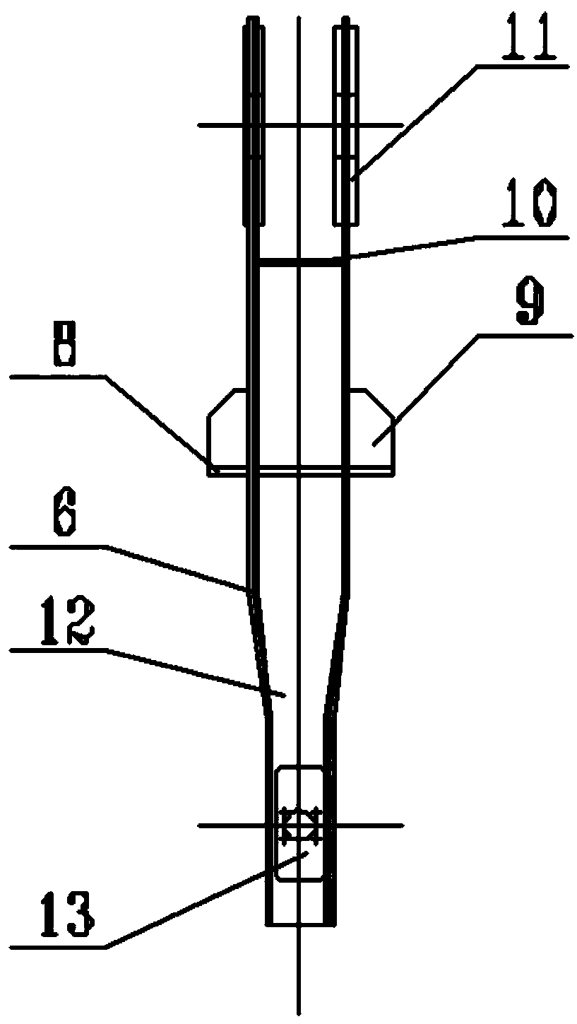
[0022] Please refer to Figure 1-6 : First, from figure 1 We can see that the pull rods of the gate and the trash rack of the present invention are formed by connecting multiple pull rod units in series. Axis 3 is connected, the bottom of the tie rod is connected to the gate or trash rack, and the top of the tie rod is connected to the gate or trash rack hoist head through the lifting hole. The bottom section of the lower tie rod 2 is connected to the lifting lug 4 of the gate or trash rack through the pin shaft 3; the topmost section of the upper tie rod 1 is connected to the hoisting device such as the lifting head of the winch hoist through the tie rod hanging hole .

[0023] In the present invention, the structures of the upper tie rod...


PUM


Abstract

The invention discloses a method and structure for improving a pull rod of a gate or a trash rack. According to the method, an upper pull rod section and a lower pull rod section which are connected with the gate or the trash rack are connected through a hinge pin perpendicular to the upper pull rod section and the lower pull rod section, so that the upper pull rod section and the lower pull rod section deflect in perpendicular directions, wherein one pull rod section deflects under the effect of an external factor such as displacement of a locking beam or vibration of the gate or the trash rack; and the other pull rod section connected with the deflected pull rod bears force in a direction perpendicular to the deflection direction, so that the friction force between the hinge pin and thepull rod is increased, the pull rod section is prevented from deflecting in the same direction, the influence of the deflection of the pull rod section on the deflection of the whole pull rod is greatly reduced, the accident that a fixing bolt is sheared off due to the large force borne by the hinge pin of the pull rod, and consequentially, the hinge pin is separated from the pull rod is prevented, and the operating safety of the pull rod is effectively improved.

Description

technical field [0001] The invention relates to an improvement method and structure of a gate and a trash rack tie rod, belonging to the technical field of metal structures of water conservancy and hydropower projects. Background technique [0002] For gates and trash rack tie rods, the connected upper and lower tie rods are generally connected by pins arranged in the same direction, and the deflection direction of all the tie rods is the same. There is a problem that one of the tie rods is affected by external factors such as the displacement of the locking beam, the gate Or the vibration of the trash rack deflects, and all the tie rods are deflected in one direction, which will cause a large amount of deflection of the overall tie rod, and sometimes cause part of the pin shaft to shear off the fixing bolt due to a large force, and the pin shaft will be detached from the tie rod. Accidents cause losses, and the difficulty of maintenance in the later stage is also relatively...

Claims


Application Information

Patent Timeline
Patent Type & Authority Applications(China)
IPC IPC(8): E02B7/20E02B8/02
CPCE02B7/20E02B8/023
Inventor 王兴恩
Owner CHINA POWER CONSRTUCTION GRP GUIYANG SURVEY & DESIGN INST CO LTD
Learn More