A printing machine with cleaning function

A printing machine and functional technology, which is applied in the field of printing machines with cleaning function, can solve the problems of paper adsorption, loss of paper patterns, and decline in paper aesthetics, and achieve the effect of avoiding damage to paper and avoiding damage

Active Publication Date: 2020-07-03
温州劲嘉彩印有限公司
View PDF17 Cites 0 Cited by
  • Summary
  • Abstract
  • Description
  • Claims
  • Application Information

AI Technical Summary

Problems solved by technology

[0003] However, after the production of existing paper is completed, there are generally some scraps left on it. If the scraps are not dealt with and then printed directly with the printing device, then it will appear that the printed pigments are actually printed on the scraps. Therefore, in the subsequent use of the paper, the debris will be washed away, so the pigment attached to it will also be washed away, which will cause the pattern on the paper to be partially missing, making the appearance of the paper sharply Therefore, before the paper enters the bottom of the printing device, a process of removing lint is required. In the prior art, an absorbing roller is generally used to roll over the paper, so as to absorb the debris on the paper and complete the process for Debris cleaning, but this method can only clean one side of the debris in one cleaning process. At the same time, when some soft paper is given for cleaning, it is easy to have the problem of absorbing paper

Method used


Image

  • A printing machine with cleaning function
  • A printing machine with cleaning function

Examples


Embodiment approach

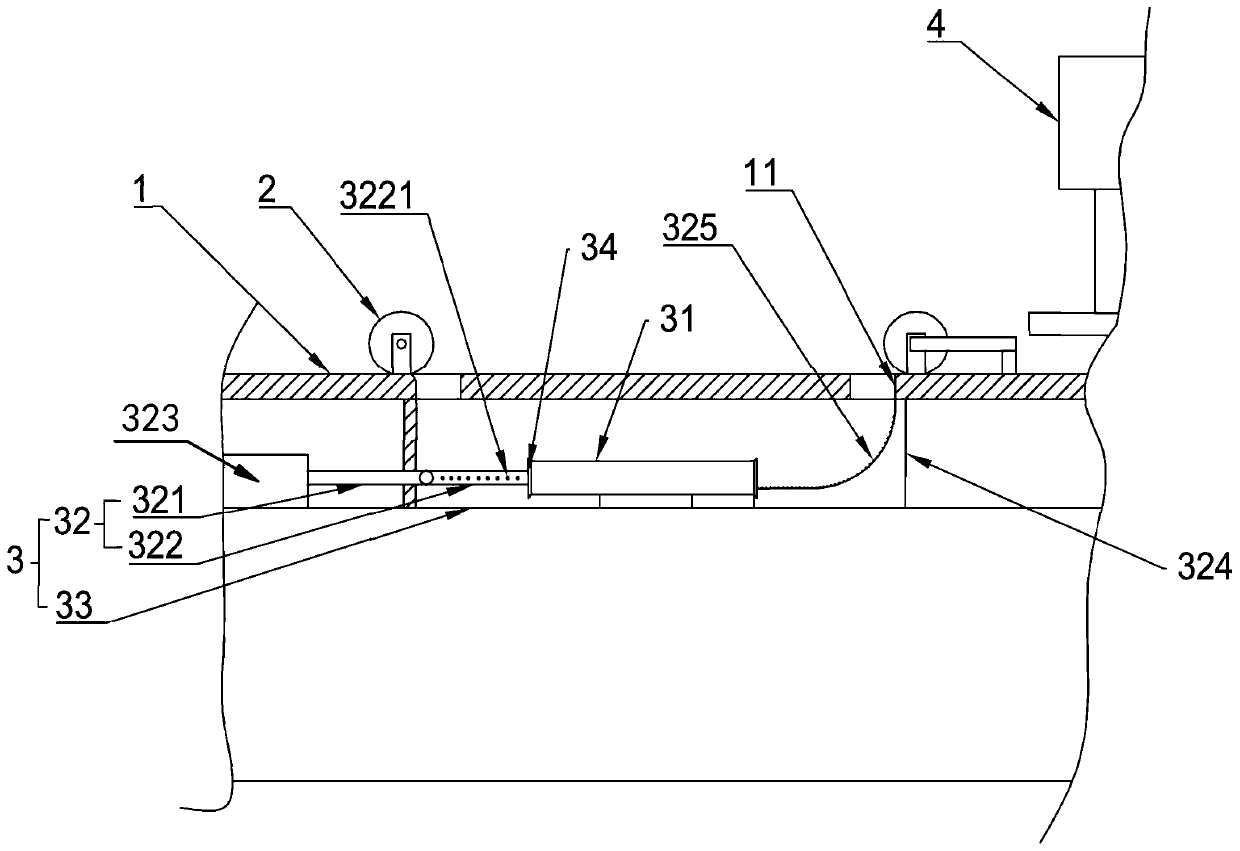
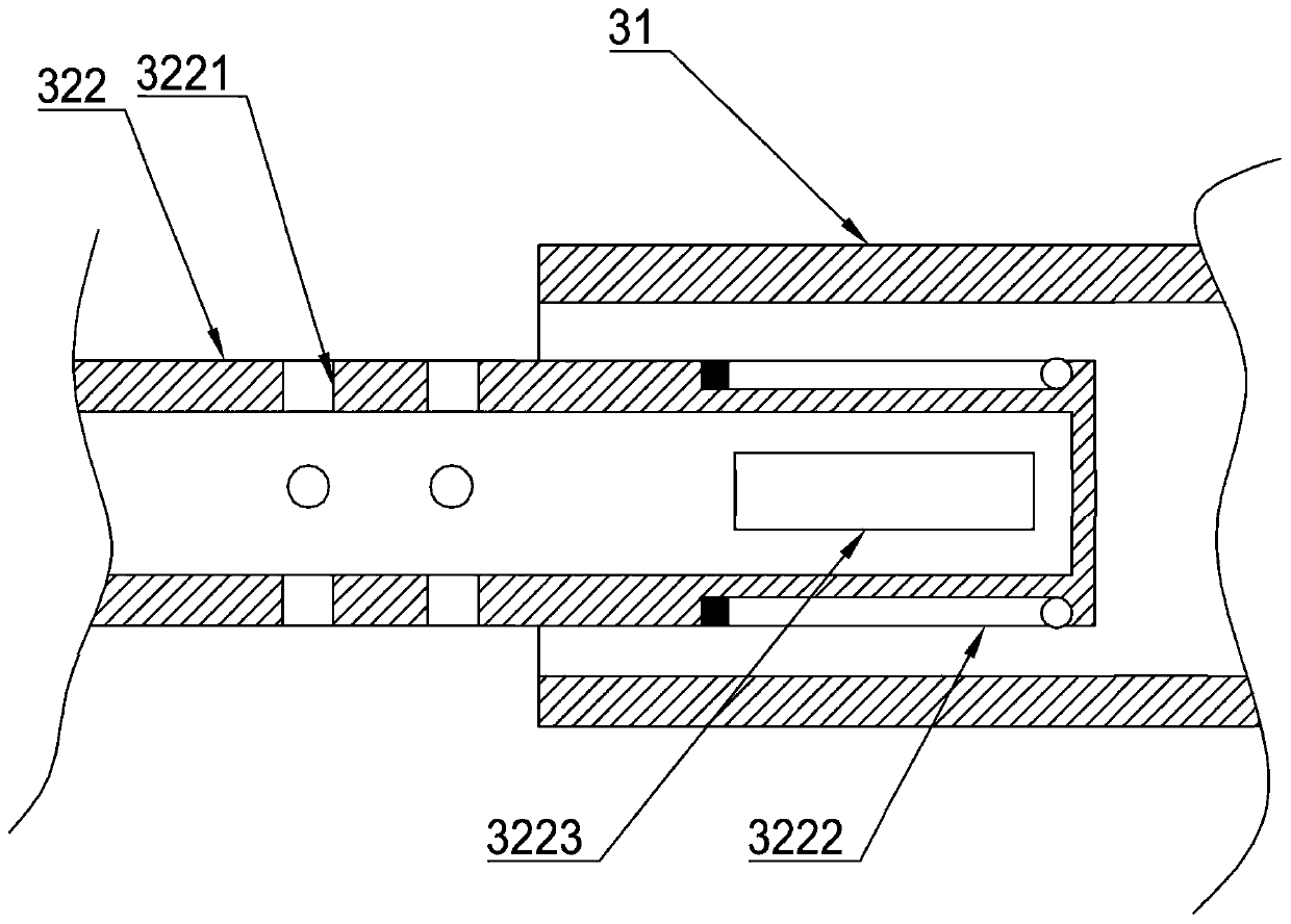
[0016] As an improved specific embodiment, the cleaning column 32 includes a base column 321 and a turning column 322, and a cleaning cylinder 323 is provided at a position below the frame 1 relative to the paper conveying device 2, and the cleaning cylinder 323 The cylinder body is fixed on the cleaning table 33, the base column 321 is coaxially fixed on the push rod of the cleaning cylinder 323, and the crutch column 322 is elastically hinged on the end of the base column 321 facing away from the cleaning cylinder 323, and the frame 1 A turning track 324 is provided below the printing device 4, and the turning track 324 is arranged relative to the end of the cleaning sleeve 31, so that when the cleaning cylinder 323 drives the cleaning column 32 to stretch out from the cleaning sleeve 31 with paper, The turning column 322 is turned upwards, and several air outlet holes 3221 are provided on the side wall of the turning column 322. When the turning column 322 is turned upwards ...


PUM


Abstract

The invention discloses a printer with a cleaning function. The printer with the cleaning function comprises a rack, a cloth conveying device, a cleaning device and a printing device, wherein the cloth conveying device, the cleaning device and the printing device are sequentially arranged on the rack. Cloth is conveyed by the cloth conveying device into the cleaning device so as to be cleaned, andthen the cleaned cloth is conveyed by the cloth conveying device into the printing device so as to be printed. The cleaning device comprises a cleaning table, a cleaning sleeve and a cleaning column.The cleaning table is arranged at the position, between the cloth conveying device and the printing device, of the rack. The cleaning sleeve is fixed to the cleaning table, and the two ends of the cleaning sleeve are separately opposite to the cloth conveying device and the printing device. The cleaning column is slidably arranged at the position, close to the cloth conveying device, of the cleaning table and is arranged opposite to the end, opposite to the cloth conveying device, of the cleaning sleeve. According to the printer with the cleaning function, both sides of a piece of cloth can be cleaned effectively through the cleaning sleeve and the cleaning column.

Description

technical field [0001] The invention relates to a printing machine, in particular to a printing machine with cleaning function. Background technique [0002] In the process of paper production, for the aesthetics of the paper, the general paper manufacturers will choose to print some more attractive patterns on the paper to increase the aesthetics of the paper. However, the existing printing methods for paper generally choose equipment For automatic printing, a conveying device is set to continuously convey the paper to the bottom of a printing device, and then the printing device is used to print the paper, so as to realize automatic paper printing. [0003] However, after the production of existing paper is completed, there are generally some scraps left on it. If the scraps are not dealt with and then printed directly with the printing device, then it will appear that the printed pigments are actually printed on the scraps. Therefore, in the subsequent use of the paper, ...

Claims


Application Information

Patent Timeline
Patent Type & Authority Patents(China)
IPC IPC(8): B41F22/00
CPCB41F22/00
Inventor 章圣放蔡成状
Owner 温州劲嘉彩印有限公司
Why Eureka
Try Eureka