Preheat rotary injection molding die mechanism for injection molding machine

An injection mold and preheating technology, applied in the field of injection molding machine preheating rotary injection mold mechanism, can solve the problems of long heating time, troublesome, low efficiency, etc., and achieve the effect of good injection molding effect, guaranteed effect and high efficiency.

Inactive Publication Date: 2019-01-11
DONGGUAN SHENGRONG AUTOMATION TECH CO LTD
View PDF5 Cites 2 Cited by
  • Summary
  • Abstract
  • Description
  • Claims
  • Application Information

AI Technical Summary

Problems solved by technology

[0002] In the existing small injection molding machines, it generally only has one injection mold. After injecting the injection material into the injection mold through the injection nozzle, the injection mold needs to be opened to take out the material, and then the subsequent injection molding is very troublesome and inefficient. continuous production;
[0003] At the same time, before injection molding, in order to ensure the injection molding effect, the mold needs to be heated, and the existing mold generally needs to be heated before installation, which is very troublesome, especially in winter, the heating time is long, and after one injection molding is completed, the next For one, when the temperature of the mold is not enough, it needs to be disassembled and heated, which is quite troublesome

Method used


Image

  • Preheat rotary injection molding die mechanism for injection molding machine
  • Preheat rotary injection molding die mechanism for injection molding machine
  • Preheat rotary injection molding die mechanism for injection molding machine

Examples


Embodiment Construction

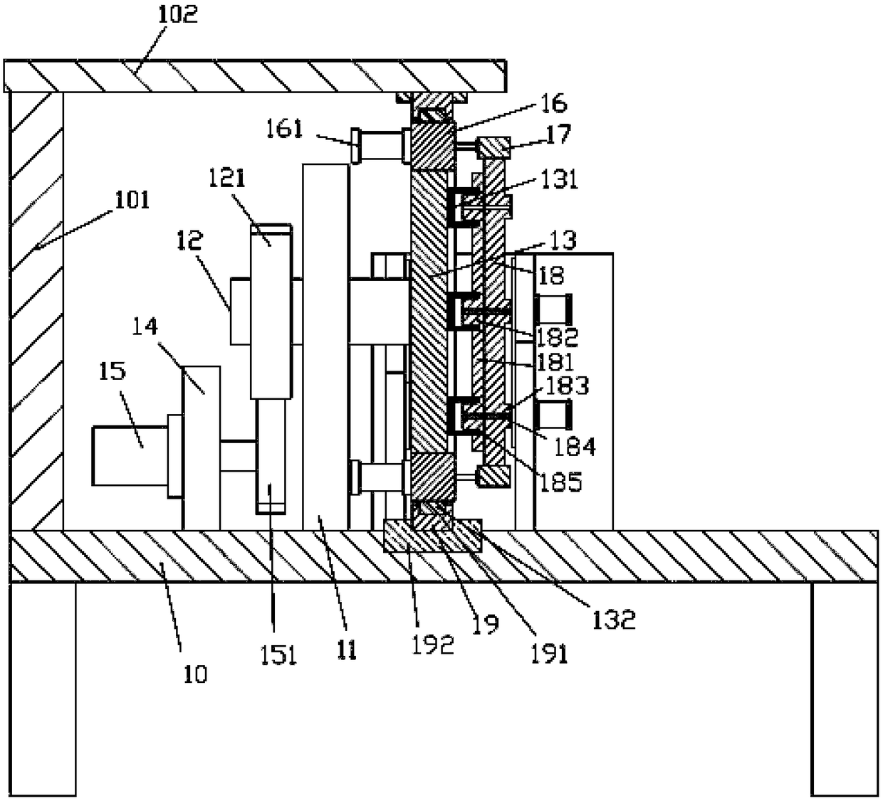
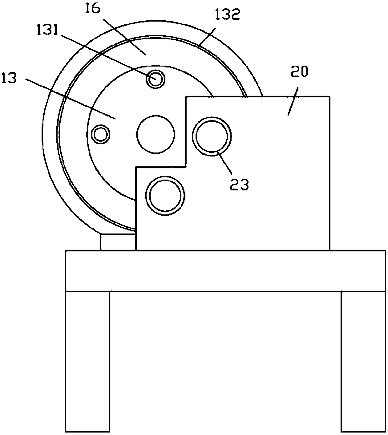
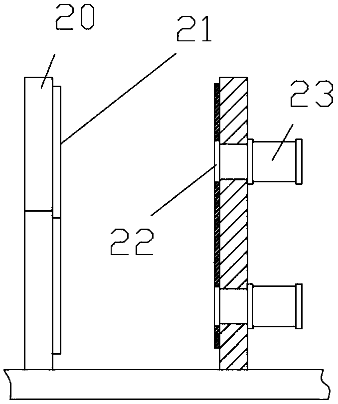
[0019] Examples, see e.g. Figure 1 to Figure 3 As shown, a preheating rotary injection mold mechanism for an injection molding machine includes a frame 10, a main vertical plate 11 is fixed on the top surface of the top plate of the frame 10, and the rear right side of the main vertical plate 20 is Two vertical fixed plates 20 are fixed on the top surface of the top plate of the frame 10, and heating plates 21 are fixed on the opposite wall surfaces of the two vertical fixed plates 20. The middle part of the main vertical plate 11 is hinged with a horizontal main shaft 12, and The right end of the main shaft 12 protrudes from the main vertical plate 11 and is fixed with a rotating disk 13. A plurality of left injection molds 131 are fixed on the right side wall of the rotating disk 13. All the left injection molds 131 are evenly distributed around the horizontal main shaft 12. On the rotating disk 13, the left end of the transverse main shaft 12 stretches out the main vertica...


PUM


Abstract

The invention discloses a preheat rotary injection molding die mechanism for an injection molding machine. The injection molding die mechanism comprises a rack, wherein a main vertical plate is fixedat the top of the rack; two vertical fixing plates are fixed at the top of the roof of the rack and at the rear part of the right side of the main vertical plate; heat plates are fixed on two oppositewall surfaces of the two vertical fixing plates; a transverse main shaft is hinged with the center of the main vertical plate; and the right end of the traverse main shaft extends out of the main vertical plate, and a rotary plate is fixed at the right end of the transverse main shaft. According to the preheat rotary injection molding die mechanism, a plurality of left injection molding dies arearranged on the rotary plate, after injection molding in one left injection molding die is completed, the rotary plate is immediately rotated to the next left injection molding die for injection molding, continuous injection molding is realized along with good effect and high efficiency, and the left injection molding dies and right convex die blocks to be about to injection molding can be preheated to ensure the temperature for the dies during injection molding, so that the injection molding effect can be ensured.

Description

Technical field: [0001] The invention relates to the technical field of injection molding equipment, in particular to a preheating rotary injection mold mechanism for an injection molding machine. Background technique: [0002] In the existing small injection molding machines, it generally only has one injection mold. After injecting the injection material into the injection mold through the injection nozzle, the injection mold needs to be opened to take out the material, and then the subsequent injection molding is very troublesome and inefficient. continuous production; [0003] At the same time, before injection molding, in order to ensure the injection molding effect, the mold needs to be heated, and the existing mold generally needs to be heated before installation, which is very troublesome, especially in winter, the heating time is long, and after one injection molding is completed, the next For one thing, when the temperature of the mold is not enough, it needs to b...

Claims


Application Information

Patent Timeline
Patent Type & Authority Applications(China)
IPC IPC(8): B29C45/06B29C45/73
CPCB29C45/06B29C45/73
Inventor 孙杏花
Owner DONGGUAN SHENGRONG AUTOMATION TECH CO LTD
Why Eureka
Try Eureka