
An Electron Beam Welding Method for Large Thickness Inclined Angle Welds

A technology of electron beam welding and tilting angle, which is applied in the direction of electron beam welding equipment, welding equipment, metal processing equipment, etc., can solve the problems of non-fusion, inconvenient operation, welding deviation at the root of large-thick weld seam, etc., and achieve the goal of avoiding tilting angle Influence, prevent non-fusion defects, and ensure the effect of welding quality

Active Publication Date: 2020-11-20
CAPITAL AEROSPACE MACHINERY +1
View PDF5 Cites 0 Cited by
  • Summary
  • Abstract
  • Description
  • Claims
  • Application Information

AI Technical Summary

Problems solved by technology

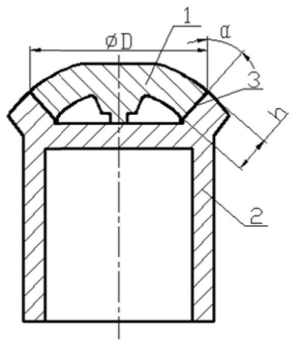
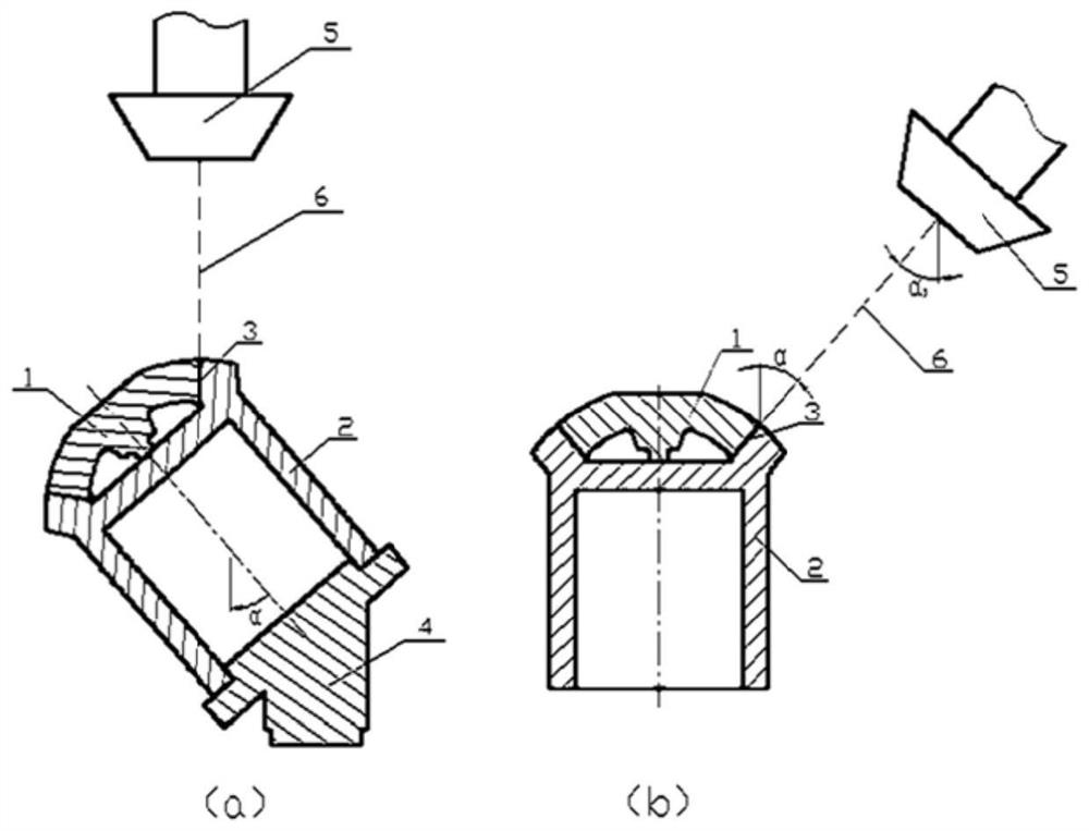
The electron gun 5 is placed vertically, and the electron beam 6 emitted from the electron gun is vertically downward beamed. The inclination angle α of the workpiece makes the welding seam in a vertical orientation. The method of inclining the workpiece needs to be adjusted by clamping the welding tool 4 with a three-jaw chuck. (When the three-jaw chuck table of the equipment cannot be shifted and turned over), the operation is inconvenient, and the alignment of the weld seam is affected by the positioning accuracy of the tooling
Electron beam welding due to workpiece inclination angle error affects the consistency of the beam path of the electron beam and the position of the weld seam, and if the weld section width is not properly controlled and is too narrow, it is easy to cause the root of the large-thick weld seam Defects such as welding deviation and lack of fusion cannot meet the welding quality requirements

Method used


Image

  • An Electron Beam Welding Method for Large Thickness Inclined Angle Welds
  • An Electron Beam Welding Method for Large Thickness Inclined Angle Welds
  • An Electron Beam Welding Method for Large Thickness Inclined Angle Welds

Examples


Embodiment Construction

[0039] The present invention will be further described below in conjunction with the accompanying drawings.

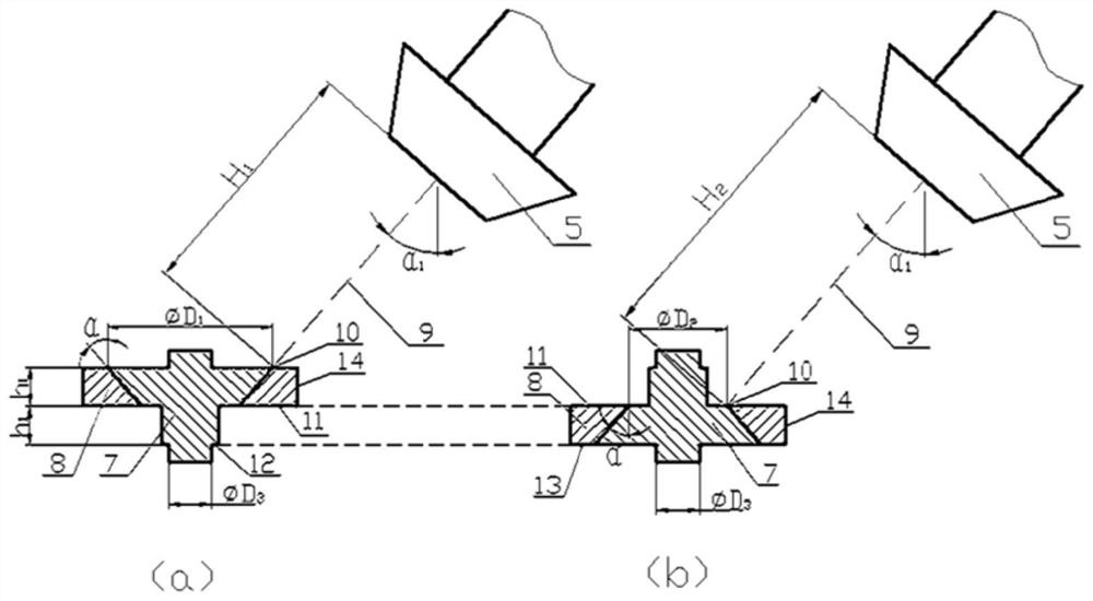
[0040] Figure 4 It is the process flow diagram of the present invention, adopting the inclined electron gun welding method to carry out the electron beam welding of the large-thickness inclined-angle weld seam, and avoid the method of welding defects such as welding deviation and lack of fusion, including the following steps:

[0041]Step 1. Process the inner sample block 7 and the outer sample block 8 according to the inclined weld angle α and the welding thickness h marked on the drawings. The outer sample block 8 is a ring structure, and the inner wall is a conical surface; the inner sample block 7 is a multi-section structure, the first section is a conical frustum structure, and a raised structure is set in the center of the large end of the conical frustum, and the second and third sections are cylinders respectively. structure, the diameter of the second secti...


PUM


Abstract

The invention discloses an electron beam welding method for a large-thickness inclined-angle welding joint. The electron beam welding method for the large-thickness inclined-angle welding joint comprises the following steps: step 1, machining an inner sample piece (7) and an outer sample piece (8); step 2, assembling the inner sample piece (7) and the outer sample piece (8) to form a sample pieceassembly; step 3, setting an inclined angle alpha 1 of an electronic gun, controlling the electronic gun (5) to carry out inclination action, and inspecting the accuracy of the inclined angle alpha 1of the electronic gun by virtue of the sample piece assembly; step 4, assembling an upper weldment (1) and a lower weldment (2) of a part to be welded, and demarcating the joint positions of the upperweldment (1) and the lower weldment (2); step 5, setting a beam current of the electron beam, rotating the part to be welded, and carrying out centering and alignment on a welding track; step 6, determining the root width W of the large-thickness inclined-angle welding joint according to a welding thickness and various deviation factors; and step 7, welding the inclined welding joint (3). According to the electron beam welding method for the large-thickness inclined-angle welding joint, the problems of welding defects of welding deviation, incomplete fusion and the like for the root of the large-thickness inclined-angle welding joint, are solved.

Description

technical field [0001] The invention relates to an electron beam welding method. Background technique [0002] The high-thrust hydrogen-oxygen supplementary combustion engine of the heavy-duty launch vehicle adopts a pre-combustion chamber structure, and the material is a high-temperature alloy GH4169. Since the pressure of the pre-combustion chamber reaches 33MPa, the welding thickness is designed to be thicker, generally reaching more than 20mm. Conventional fusion welding cannot meet the requirements of controlling deformation and effectively ensuring connection strength. Vacuum electron beam welding is an advanced welding technology, suitable for welding large thickness welds. Due to the limitation of the structural position, in order to avoid the shielding of the electron beam by the welding path, the joint structure of the multi-pass weld is designed as a butt weld with an inclined angle. The so-called oblique angle weld means that when the workpiece to be processed ...

Claims


Application Information

Patent Timeline
Patent Type & Authority Patents(China)
IPC IPC(8): B23K15/00
CPCB23K15/0006B23K15/0033B23K15/0053
Inventor 谢美蓉张益坤朱瑞灿陈靖李跃王炜田越赵刚张净刘敏
Owner CAPITAL AEROSPACE MACHINERY
Learn More