
Lens film stripping equipment

A technology of film removal and equipment, which is applied in the direction of chemical instruments and methods, cleaning methods and utensils, cleaning methods using liquids, etc. It can solve the problems of inability to remove film color on the lens surface, limited level of film removal technology, and high cost of nitrate materials. , to achieve the effect of promoting reprocessing after stripping, reducing the number of scrapped products, and improving economic benefits

Inactive Publication Date: 2019-01-11
孟凡清
View PDF8 Cites 1 Cited by
  • Summary
  • Abstract
  • Description
  • Claims
  • Application Information

AI Technical Summary

Problems solved by technology

[0002] During the industrial coating process of lenses, due to the influence of some objective factors, such as human anomalies, coating material problems, coating process problems, power outages, etc., there will be a certain proportion of defective products that need to be reworked. However, due to modern optical coating medicinal materials There are many ingredients and specifications, and the level of stripping technology is limited, resulting in many lens surface film colors that cannot be removed. When the traditional polishing process directly repairs the lens, the hardness of the coating medicinal material is much greater than that of the glass and its characteristics. Not only the processing time is long, but also Due to processing, eccentricity, small diameter and other adverse effects will result in many scrapped products, especially for tight delivery, high cost of glass materials, and some special lenses, which will cause huge waste, and after scrapping, they must be purchased from raw materials. The first process starts processing later, which wastes resources. If this part of the product can be directly stripped to meet the appearance and function requirements, it can be repaired in the way of uncoated products, and even after stripping, the coating can be cleaned directly ( Not other bad, just poor coating), which will greatly improve efficiency and benefit

Method used


Image

  • Lens film stripping equipment

Examples


Embodiment Construction

[0016] The present invention will be described in detail below through embodiments in conjunction with the accompanying drawings.

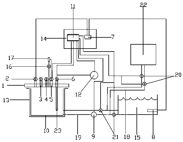
[0017] As shown in the figure, this embodiment provides a lens stripping equipment, a lens stripping equipment, including a reactor body 13, an electrical box 14 and a PLC 11, and a temperature sensing probe 2 is connected to the lid 1 of the reactor , Automatic pressure relief explosion-proof valve 3, pressure gauge 4, air release solenoid valve 5 and intake solenoid valve 6, wherein the reaction kettle is a simple reaction kettle that can quickly open the door.

[0018] The temperature sensing probe 2 is connected to a thermostat 7, and the thermostat 7 is connected to the heating pipe 8 inside the hot water tank 15 to form an automatic temperature control system that can be set. The thermostat 7 realizes automatic temperature control through PLC11. The kettle cover 1 is connected to the high-pressure air pump 12 through the air intake electroma...


PUM


Abstract

The invention discloses a lens film stripping device. The device comprises a reaction kettle body, an electric box and a PLC; and a kettle cover of a reaction kettle is connected to a temperature sensing probe, an automatic pressure relief anti-explosion valve, a pressure gauge, a manual air release valve, an air release electromagnetic valve and an air inlet electromagnetic valve. According to the lens film stripping equipment, the structure is simple and reasonable, the effect of film stripping can be effectively guaranteed, and the operation safety can be improved through the automatic pressure relief anti-explosion valve; meanwhile automatic temperature control and coil pipe type heating mode are adopted, the PLC is used for programmable control, the automation level is improved, and an extremely good condition is created for batch production; and the processing of a coating film product after stripping is promoted, the efficiency is improved, and the economic benefits of optical lens processing are improved.

Description

technical field [0001] The invention belongs to the technical field of lens production, and in particular relates to a technical process for removing a film from a lens after vacuum coating, and in particular to a lens removing device. Background technique [0002] During the industrial coating process of lenses, due to the influence of some objective factors, such as human anomalies, coating material problems, coating process problems, power outages, etc., there will be a certain proportion of defective products that need to be reworked. However, due to modern optical coating medicinal materials There are many ingredients and specifications, and the level of stripping technology is limited, resulting in many lens surface film colors that cannot be removed. When the traditional polishing process directly repairs the lens, the hardness of the coating medicinal material is much greater than that of the glass and its characteristics. Not only the processing time is long, but als...

Claims


Application Information

Patent Timeline
Patent Type & Authority Applications(China)
IPC IPC(8): B08B3/08B08B3/10B08B13/00C03C23/00
CPCB08B3/08B08B3/10B08B13/00B08B2203/007C03C23/00C03C23/0075
Inventor 孟凡清
Owner 孟凡清
Learn More