
Fast and uniform dilution device for polymer concentrated solution

A dilution device and high polymer technology, which is applied in the field of rapid and uniform dilution of high polymer concentrated solution, can solve the problems of increasing the load of the aircraft, not being suitable for drag reduction, and being unable to carry a large amount of high polymer dilute solution, etc., to achieve the goal of quality Effect

Active Publication Date: 2019-01-11
NORTHWESTERN POLYTECHNICAL UNIV
View PDF7 Cites 5 Cited by
  • Summary
  • Abstract
  • Description
  • Claims
  • Application Information

AI Technical Summary

Problems solved by technology

[0003] Chinese patent CN105947105A discloses "a mucus drag reducing device for an underwater vehicle". The mucus drag reducing device is sprayed with a pre-prepared polymer solution. The solution is not suitable for drag reduction for a long time; in the invention patent CN102923247A, a new method for reducing the running and launching resistance of underwater ships, torpedoes and underwater missiles by using high polymers is proposed. Polymer dry material hot extrusion produces dry film shell, polymer concentrated solution film and polymer solution soaking in various implementations, but these methods cannot control the release rate according to the actual cruising state of the aircraft, and are not suitable for long-term cruising
However, due to the limited space available in the aircraft cabin, it is impossible to carry a large amount of dilute polymer solution

Method used


Image

  • Fast and uniform dilution device for polymer concentrated solution

Examples


Embodiment Construction

[0022] This embodiment is a device for rapid and uniform dilution of high polymer concentrated solution.

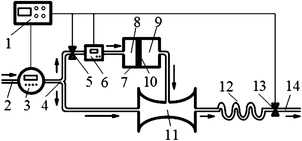
[0023] refer to figure 1 , the high polymer concentrated solution rapid and uniform dilution device in this embodiment, when the controller 1 obtains the external dilution command, calculates according to the injection rate and concentration requirements of the required high polymer dilute solution, and outputs the corresponding signal. The high polymer concentrated solution rapid and uniform dilution device consists of a controller 1, a water diversion pipe 2, a metering pump 3, a branch pipe 4, an electric valve 5, an electromagnetic flowmeter 6, a storage chamber 8, an upstream chamber 9, a downstream chamber 10, a mixing chamber Section 11, elbow section 12, solenoid valve 13, output pipe. After the controller 1 receives the external dilution command, it outputs a control signal, and each component automatically starts and adjusts after receiving the corresponding si...


PUM


Abstract

The invention discloses a fast and uniform dilution device for a polymer concentrated solution, wherein the fast and uniform dilution device consists of a controller, a metering pump, an electromagnetic flowmeter, a storage room, a mixing section and an elbow section. The controller receives external dilution instructions and outputs control signals; a water diversion pipe is divided into two waysfor output through the metering pump via branch pipes, and one way is connected with a storage room and enters the mixing section, and the other way is connected with the mixing section and is successively connected with the elbow section, a solenoid valve and an output pipe. The storage room is used for storing the pre-prepared polymer concentrated solution, and the interior of the storage roomis divided into an upstream chamber and a downstream chamber which are separated by a piston. Water outputted from one of the branch pipes enters the upstream chamber through an electric valve and theelectromagnetic flowmeter, and the piston moves so that the polymer concentrated solution is replaced from the downstream chamber; the outputted concentrated solution enters the mixing section via the pipeline; the other way of water outputted by the branch pipes enters the mixing section and is mixed with the concentrated polymer solution and output is achieved. An underwater aircraft using thedilute polymer solution for drag reduction has great engineering application value.

Description

technical field [0001] The invention relates to the technical field of underwater drag reduction, in particular to a device for quickly and uniformly diluting high polymer concentrated solution. Background technique [0002] The polymer additive drag reduction method only needs to add a small amount of polymer in the turbulent flow field to achieve a significant drag reduction effect, even as high as 80%, and is easy to implement. It is a recognized and efficient drag reduction method. It has been popularized and applied in many fields such as pipeline transportation and central heating. The method of spraying the dilute high polymer solution to the working fluid in the pipeline through the spray tank also has the effect of drag reduction, and compared with the high polymer solution of the same concentration, the drag reduction effect of spraying is even better. Therefore, the polymer dilute solution injection method is a potential drag reduction and energy saving method fo...

Claims


Application Information

Patent Timeline
IPC IPC(8): B01F15/04B01F13/10B01F3/08B01F15/00
CPCB01F23/483B01F23/451B01F33/821B01F35/2209B01F35/83
Inventor 胡海豹任刘珍鲍路瑶张庆辉文俊黄炤源张文云
Owner NORTHWESTERN POLYTECHNICAL UNIV
Learn More