A pulse generating circuit

A technology for generating circuits and pulses, applied in the field of electronic technology, can solve the problems of low circuit power, low signal power spectral density, long recovery time of pulse circuits, etc., and achieve the effect of high work efficiency

Active Publication Date: 2022-06-24
浙江优勝科技有限公司
View PDF8 Cites 0 Cited by
  • Summary
  • Abstract
  • Description
  • Claims
  • Application Information

AI Technical Summary

Problems solved by technology

[0002] With the rapid development of science and technology, the ultra-wideband technology used in radar systems has gradually entered everyone's field of vision. With the development and wide application of wireless communication technology, spectrum resources have become more and more precious. UWB technology is called UWB technology, which has the characteristics of low power consumption, strong anti-interference ability, good confidentiality, and large capacity. However, the power spectral density of UWB signals is low, so the generation of high-speed narrow pulses It is a key technology. The pulse is realized by the pulse generating circuit. The core of the generating circuit is the triode and the current limiting resistor. The current limiting resistor in the commonly used generating circuit has a large power loss, and the recovery time of the pulse circuit is longer, resulting in The power of the whole circuit is low, so it is necessary to redesign a generation circuit, use an emitter follower instead of a current limiting resistor, provide a larger charging current, and speed up the recovery of a pulse circuit.

Method used


Image

  • A pulse generating circuit

Examples


Embodiment Construction

[0022] In order to make the technical means, creation features, achievement goals and effects realized by the present invention easy to understand, the present invention will be further described below with reference to the drawings and specific embodiments.

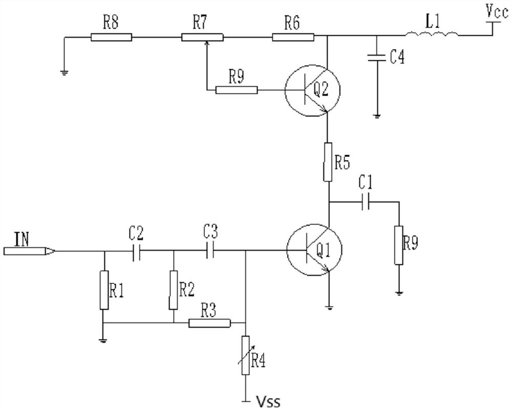
[0023] refer to figure 1 As shown, the pulse generating circuit includes a differential shaping circuit and an emitter follower, and the differential shaping circuit includes a resistor R1, a resistor R2, a resistor R3, a capacitor C2 and a capacitor C3;

[0024] The generating circuit also includes an extension interface IN, a negative power supply Vss, a positive power supply Vcc, a sliding rheostat R4, a transistor Q1, an energy storage capacitor C1, a resistor R9, a capacitor C4 and an inductor L1;

[0025] One end of the resistor R2 is connected to one end of the resistor R1 and then grounded, the other end of the resistor R1 is respectively connected to one end of the capacitor C2 and the expansion interface IN, an...


PUM


Abstract

A pulse generation circuit, including a differential shaping circuit and an emitter follower, the differential shaping circuit includes a resistor R1, a resistor R2, a resistor R3, a capacitor C2, and a capacitor C3; the generating circuit also includes an expansion interface IN, a negative power supply Vss, positive power supply Vcc, sliding rheostat R4, transistor Q1, energy storage capacitor C1, resistor R9, capacitor C4 and inductance L1; the overall working efficiency of the circuit is high, by adjusting the resistance of the rheostat box R7, the voltage of the base of the transistor Q2 Changes can flexibly change the working voltage of the triode.

Description

technical field [0001] The invention relates to the field of electronic technology, in particular to a pulse generating circuit. Background technique [0002] With the rapid development of science and technology, the ultra-wideband technology previously used in radar systems has gradually entered everyone's field of vision. With the development and wide application of wireless communication technology, spectrum resources have become more and more valuable. Ultra-wideband technology is called UWB technology, which has the characteristics of low power consumption, strong anti-interference ability, good confidentiality, and large capacity. However, the power spectral density of UWB signals is low, so the generation of high-speed narrow pulses It is a key technology. The pulse is realized by the pulse generation circuit. The core of the generation circuit is the transistor and the current limiting resistor. The current limiting resistor in the commonly used generation circuit ha...

Claims


Application Information

Patent Timeline
Patent Type & Authority Patents(China)
IPC IPC(8): H03K5/01
CPCH03K5/01
Inventor 何立刚
Owner 浙江优勝科技有限公司
Why Eureka
Try Eureka