
Wine barrel

A technology of wine barrels and wine outlets, which is applied in the field of wine barrels, can solve the problems of wine barrels that are not easy to place, break, and poor stability, and achieve the goal of preventing vibration from being transmitted to the wine storage cavity, reasonable design, and avoiding impact Effect

Inactive Publication Date: 2019-01-08
广安市前锋区观塘镇小学校
View PDF0 Cites 0 Cited by
  • Summary
  • Abstract
  • Description
  • Claims
  • Application Information

AI Technical Summary

Problems solved by technology

Most of the commonly used wine barrels are in the shape of a waist drum, but usually the wine barrel itself is not easy to place and has poor stability, which makes it difficult to fix the wine barrel during use, placement and transportation, and is prone to tilting or breaking

Method used


Image

  • Wine barrel
  • Wine barrel

Examples


Embodiment 1

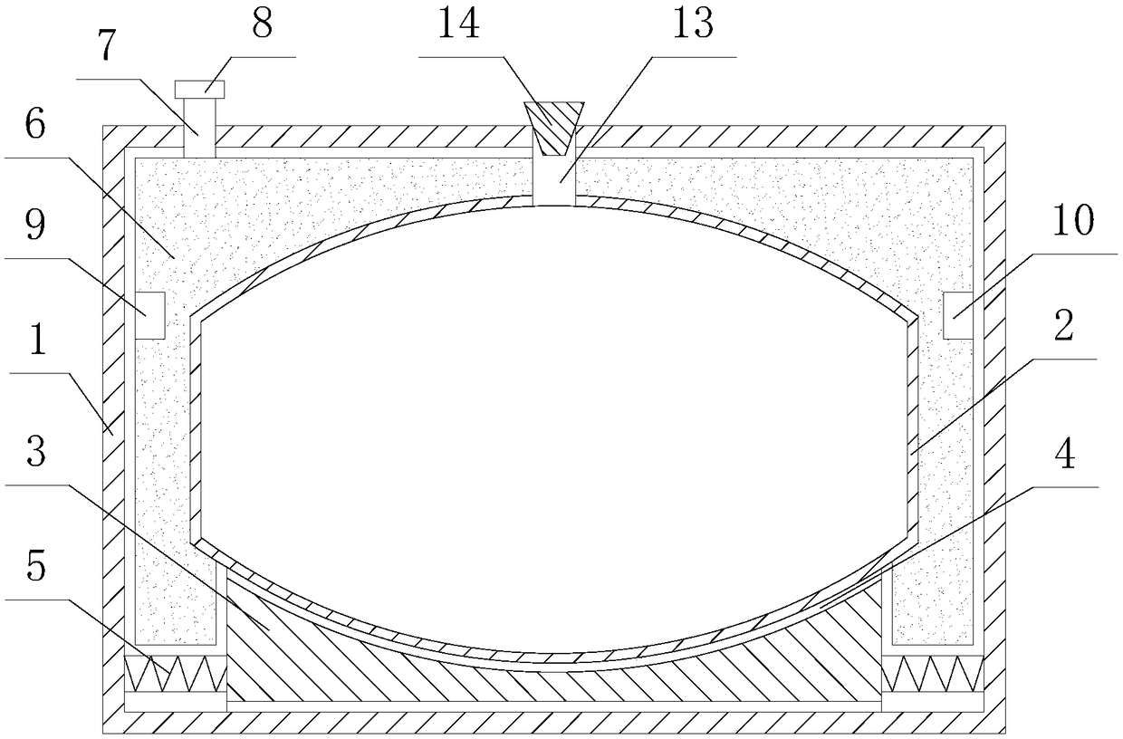
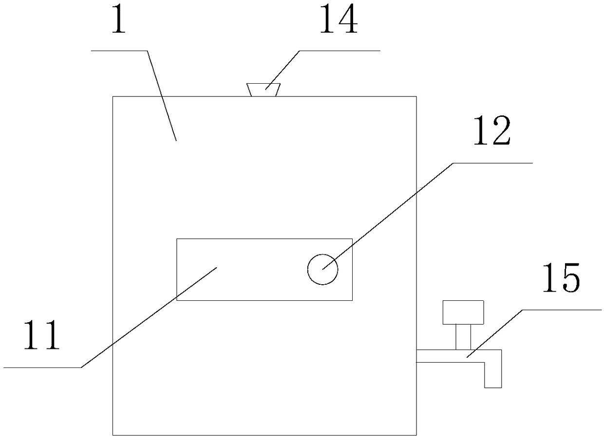
[0016] Such as figure 1 with figure 2 As shown, the wine barrel provided in this embodiment includes a stainless steel outer barrel 1 and a ceramic inner barrel 2. The stainless steel outer barrel 1 is a hollow cuboid inside. There is a placement groove 4 matching the ceramic inner barrel 2, and several evenly distributed shock-absorbing springs 5 ​​are arranged between the outer walls around the rubber shock-absorbing seat 3 and the inner wall of the stainless steel outer barrel 1, and the ceramic inner barrel 2 is placed in the placement groove. In 4, a constant temperature regulating water jacket 6 is provided between the outer wall around the ceramic inner barrel 2 and the inner wall around the stainless steel outer barrel 1, and the constant temperature regulating water jacket 6 fills the gap between the outer wall of the ceramic inner barrel 2 and the inner wall of the stainless steel outer barrel 1. The top of one side of the regulating water jacket 6 is provided with...

Embodiment 2

[0021] It is basically the same as the above-mentioned embodiment 1, except that the ceramic inner barrel 2 is changed. The ceramic inner barrel 2 is in the shape of a waist drum placed horizontally, and the inner two ends of the ceramic inner barrel 2 are respectively fixedly connected with snap rings, and the two snap rings are opposite to each other. There are card slots on the side of the card release ring, and the matching oak circular plate is seamlessly clamped in the card release ring. Several oak wood boards matching the inner wall of the ceramic inner barrel 2 are arranged between the two card release rings. The two oak boards The ends are clamped respectively in the clamping slots of the two clamping rings, and the adjacent oak boards are seamlessly connected.

[0022] The invention greatly reduces the vibration generated by the collision by setting the rubber damping seat 3 and the damping spring 5, thereby avoiding the vibration of the ceramic inner barrel 2 and en...


PUM


Abstract

A wine barrel includes a stainless steel outer barrel and a ceramic inner barrel. A rubber shock absorber seat is arranged at the inner bottom of the stainless steel outer barrel, the surface of the rubber shock absorber seat is provided with a placing groove matched with the ceramic inner barrel, a plurality of shock absorbing springs uniformly distributed are arranged between the outer wall around the rubber shock absorber seat and the inner wall of the stainless steel outer barrel. A constant temperature regulating water jacket is arranged between the outer wall around the ceramic inner barrel and the inner wall around the stainless steel outer barrel. The ceramic inner barrel is a wine storage cavity, a wine inlet is arranged at the top of the ceramic inner barrel, a wine inlet pipe isarranged at the wine inlet, an oak plug is arranged at the top of the wine inlet pipe, a wine outlet is arranged at the lower part of one side of the ceramic inner barrel, a wine outlet faucet is arranged at a position, corresponding to the wine outlet, of the stainless steel outer barrel, and the wine outlet faucet communicates with the wine outlet. The invention can effectively prevent the vibration from being transmitted into the wine storage cavity, avoid the influence of the vibration on the quality of the wine, and provide the constant temperature storage condition.

Description

technical field [0001] The invention belongs to the technical field of wine storage equipment, and in particular relates to a wine barrel. Background technique [0002] Wine barrel storage has a history of thousands of years and has profound cultural connotations. Many consumers hope to have their own wine barrels at home to store fine wine, but wine barrel storage requires low temperature environment. They are generally placed in underground wine cellars, and most families do not have such conditions. Most of the commonly used wine barrels are in the shape of a waist drum, but usually the wine barrel itself is not easy to place and has poor stability, which makes it difficult to fix the wine barrel during use, placement and transportation, and is prone to tilting or breaking. Contents of the invention [0003] The technical problem to be solved by the present invention is to provide a wine barrel with a simple structure and a reasonable design, which can be stored at a c...

Claims


Application Information

Patent Timeline
Patent Type & Authority Applications(China)
IPC IPC(8): B65D85/72B65D77/04B65D25/28B65D81/38B65D25/24B65D79/02
CPCB65D85/72B65D25/20B65D25/24B65D77/0446B65D79/02B65D81/3806
Inventor 刘刚
Owner 广安市前锋区观塘镇小学校
Learn More